Positioning Motor and Apparatus

a positioning motor and positioning device technology, applied in the field of motors, can solve the problems of limited positioning resolution of piezoelectric ultrasonic motors, inability to combine direct positioning modes, and inability to achieve direct positioning modes, and achieve optimal working efficiency and optimal efficiency.

Inactive Publication Date: 2009-10-29
KATHOLIEKE UNIV LEUVEN
View PDF5 Cites 4 Cited by
  • Summary
  • Abstract
  • Description
  • Claims
  • Application Information

AI Technical Summary

Benefits of technology

[0021]Optimal efficiency is achieved when these two vibration modes occur at the same frequency. The tuning mechanism 4 comprises a mass 4a, 4b connected to the surrounding stator module 1 with flexible or biasing elements 5a, 5b. In a preferred embodiment these flexible or biasing elements, for instance leaf springs, are stiff in horizontal direction and flexible in vertical direction. Due to this arrangement the horizontal vibration mode will change in frequency while the vertical vibration mode will remain unchanged by changing the mass 4a, 4b. Thus, the stator module can be tuned to obtain optimal working efficiency.
[0022]When the piezoelectric actuators 2a and 2b are operated with a phase difference, for example in quadrature, both the horizontal and vertical vibration mode will be excited. This will result in a closed trajectory of the contact point (B), for example elliptical. The trajectory of this contact point (B) will allow the stator module 1 to drive the driven part 6. It is clear for people skilled in the art that the working principle is not limited by vertical and horizontal vibrations. The essence is that the vibrations are perpendicular relative to each other. The drive speed of this driven part can be controlled by respectively the frequency, the amplitude and the phase of the piezoelectric actuators. Via a phase drive operation the characteristic “dead zone” is eliminated, which will allow for a precise positioning.
[0024]When piezoelectric actuators 1a and 1b are deformed in opposition by applying a DC voltage to the respective actuators, the contact point (B) is moved horizontally. The generated displacement is proportional to the applied voltage, through friction this motion is transferred to the driven part 6. The direct positioning mode allows actuating the driven part 6 over a short stroke with a high positioning resolution of movement, which is very interesting for precision applications.
[0026]One can see that if piezoelectric actuators 2a and 2b are operated at the resonance frequency in order to work in the resonant vibration mode and piezoelectric actuators 1a and 1b are actuated in the direct positioning mode, a simultaneous operation of the resonant vibration mode and the direct positioning mode is possible. The resulting motion of the contact point (B) will be a superimposed motion: an elliptical trajectory due to the high frequent vibration of the resonant vibration mode and a low-frequent horizontal motion due to the direct positioning mode. The resulting positioning performance of the driven part is also a superposition of both working modes. A high speed and large travel is achieved by working in the resonant vibration mode while the direct actuation mode will allow a high positioning resolution.

Problems solved by technology

Although several ultrasonic motors operating by a resonant vibration mode have been designed over the last years (U.S. Pat. No. 5,136,200; EP 0 313 072 A1; U.S. Pat. No. 4,613,782; U.S. Pat. No. 5,852,336; U.S. Pat. No. 6,147,436), they cannot be combined with a direct positioning mode.
However, a disadvantage of piezoelectric ultrasonic motors is their limited positioning resolution.
Piezoelectric motors of the state of the art show a strong non-linear behaviour at low speeds, which limits the performance.
This working method makes it impossible to use the described piezoelectric motor for trajectory control where at all times a fine positioning resolution is required.
Piezoelectric motors of the state of the art are incompatible with the principle proposed in this document because of its special structure.

Method used


Image

  • Positioning Motor and Apparatus
  • Positioning Motor and Apparatus
  • Positioning Motor and Apparatus

Examples


Embodiment Construction

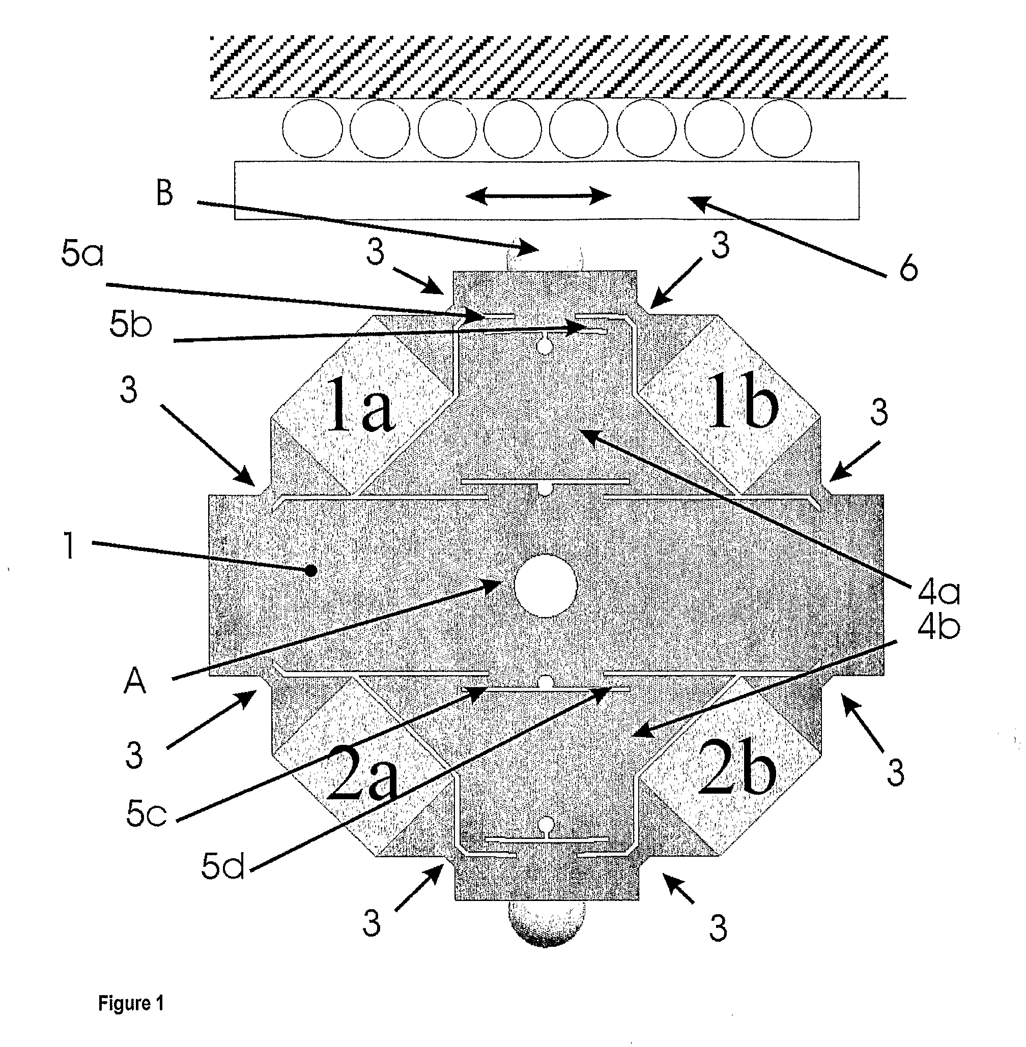
[0018]Operation of the stator module 1 of the piezoelectric motor according to the invention is based on the simultaneous operation in the resonant vibration mode and the direct positioning mode. As such the resultant motion of the driven part 6 consists of a motion caused by the resonant vibration mode and a correction motion carried out by the direct positioning mode.

[0019]1. The Resonant Vibration Mode

[0020]When piezoelectric actuators 1a and 1b or 2a and 2b are deformed in opposition, for instance anti-phase operation, at a predefined frequency, the horizontal vibration mode is excited. This will cause a strongly enlarged vibration of the contact point (B) in horizontal direction. When piezoelectric actuators 1a and 1b or 2a and 2b are deformed in identical manner, for instance phase operation, at a predefined frequency, the vertical vibration mode is excited. This will cause a strongly enlarged vibration of the contact point (B) in vertical direction.

[0021]Optimal efficiency is...


PUM


Abstract

A piezoelectric motor has a stator module 1, comprising two pairs of piezoelectric actuators Ia, Ib and 2a, 2b inside this stator module. The stator module is fixed by a central fixing point (A). The piezoelectric actuators 1a, 1b, 2a, 2b are connected to the stator module via flexible or biasing elements 3, such as for instance hinges, for instance elastic hinges. The stator module 1 comprises a tuning mechanism 4, comprising at least one mass 4a, 4b and at least one flexible or biasing element 5a, 5b, 5c, 5d, for instance leaf springs. The stator module 1 is contacted to a driven part 6, for instance a slider, at the contact point (A). The piezoelectric motor is designed such that contact point (B) is able to produce a closed trajectory, thereby inducing a relative motion of the driven part 6. The contact point (B) is moved by applying an electric field to actuators Ia and Ib and / or by applying an electric field to actuators 2a and 2b.

Description

BACKGROUND OF THE INVENTION[0001]The invention relates to a motor, more particularly a piezoelectric motor, which is designed to work simultaneously in a resonant vibration mode and a direct positioning mode. The resonant vibration mode will cause a mechanical element for instance a stator module to vibrate so that a relative movement of a driven part over a large travel is possible while the direct positioning mode will deform the stator module so that at the same time a fine motion control is possible.[0002]Each stator module comprises at least 2 actuators which are electrically excited as to provoke the resonant vibration mode or to deform the stator module for the direct positioning mode. The invention also involves a novel mechanism to optimize the working efficiency of a motor that can simultaneously operate in a resonant vibration mode and a direct positioning mode. The motor can be used as a linear motor, a rotational motor or a planar motor.STATE OF THE ART[0003]Recent tech...

Claims


Application Information

Patent Timeline
IPC IPC(8): H01L41/09H02N2/08
CPCH02N2/0025H02N2/026H02N2/0095H02N2/005
Inventor REYNAERTS, DOMINIEKVAN BRUSSEL, HENDRIKVAN DE VIJVER, WIM
Owner KATHOLIEKE UNIV LEUVEN
Why Eureka
Try Eureka