
Auto-igniter for biomass furnace

Inactive Publication Date: 2009-10-29
GREENVILLE MFG
View PDF41 Cites 6 Cited by
  • Summary
  • Abstract
  • Description
  • Claims
  • Application Information

AI Technical Summary

Benefits of technology

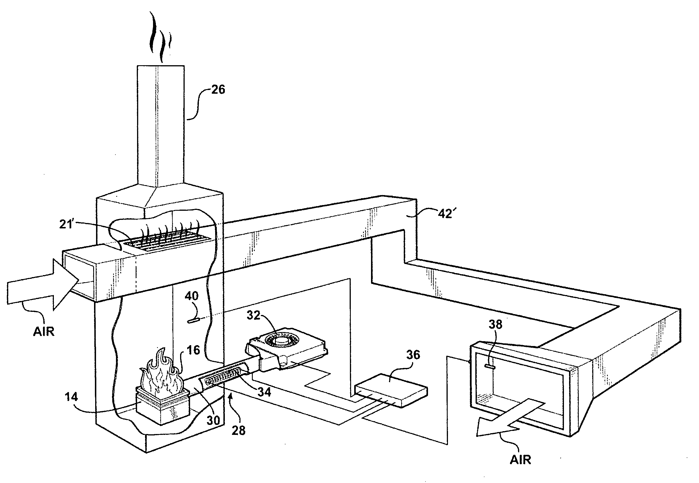
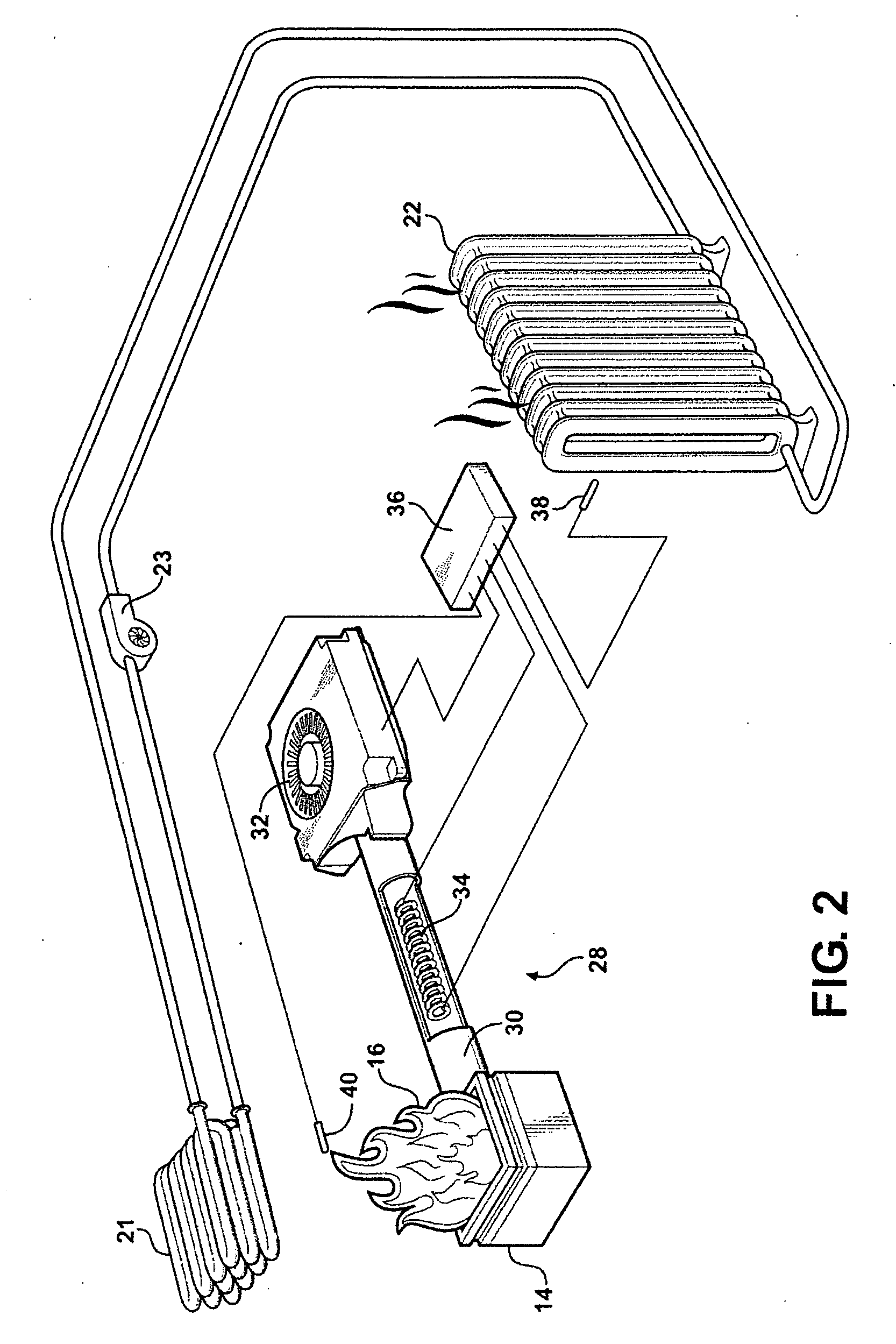
[0011]According to another aspect of this invention, a biomass furnace is provided of the type for heating an intermediate thermal fluid in response to the combustion of a biomass fuel. The furnace comprises a combustion chamber that is configured to receive biomass fuel in incremental quantities and to combust the biomass fuel therein to produce hot combustion gases. An exhaust flue is provided for conducting the hot combustion gases away from the combustion chamber. A heat exchanger, proximate the combustion chamber and / or the flue, channels a thermal fluid (e.g., air or water) to absorb heat energy from the combustion gases. A plenum leads to the combustion chamber. A fan, operatively associated with the plenum, forcibly moves air through the plenum toward the biomass fuel contained in the combustion chamber. An auxiliary heat source heats the air moved through the plenum to an elevated auto-ignition temperature. At least one temperature sensor is provided along with the control module. The control module automatically activates the auxiliary heat source in response to the temperature at the temperature sensor falling below a preset limit. Accordingly, the biomass furnace is useful in both hot water and forced air type heating systems, and enables optimal cycling on and off of the combustion process on a demand basis. When the temperature at some sensed location falls below a preset limit, the control module automatically activates the auxiliary heat source, which pumps superheated air into the biomass fuel in the combustion chamber, thereby auto-igniting the biomass fuel and restarting the combustion process.
[0014]Accordingly, the subject invention overcomes the shortcomings and disadvantages characteristic of prior art designs by providing a simple ignition system which does not require user intervention and that can rival the customary automation levels associated with prior art oil and gas-fired furnaces and boilers.

Problems solved by technology

The automation level in such stoves is very low and does not support unattended operation for extended periods.
In addition, ignition of the fuel in a biomass furnace is a somewhat complicated matter.
Ignition of the biomass fuel is so inconvenient that biomass furnaces are usually set to operate constantly at a minimum level even when there is little or no demand for heat.
Thus, at times of low demand, prior art biomass furnaces would rather waste fuel needlessly rather than inconvenience the operator to restart the combustion process.

Method used


Image

  • Auto-igniter for biomass furnace
  • Auto-igniter for biomass furnace
  • Auto-igniter for biomass furnace

Examples


Embodiment Construction

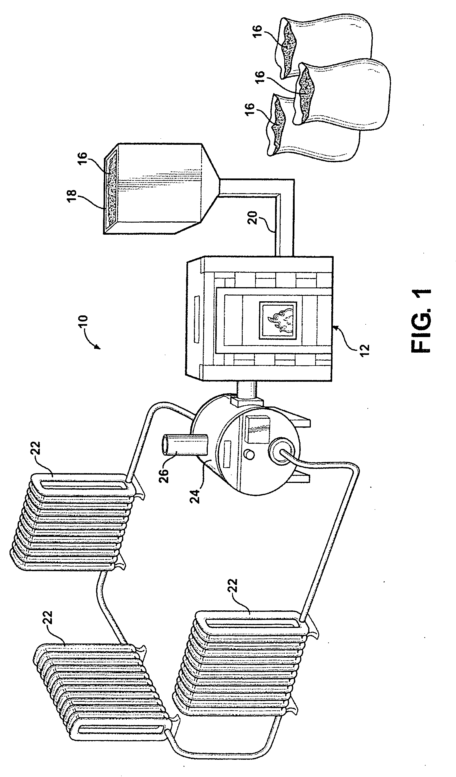
[0021]Referring to the Figures, wherein like numerals indicate like or corresponding parts throughout the several views, FIG. 1 schematically illustrates a heating system, generally shown at 10. The heating system 10 includes a biomass furnace, generally indicated at 12, which in this instance is of the boiler variety. However, it will be understood that the biomass furnace 12 could be configured to run as a forced air type heating unit, or a stand-alone stove, or other type of arrangement. The biomass furnace 12 includes a combustion chamber 14, which is perhaps best shown in FIGS. 2 and 3. The combustion chamber 14, sometimes referred to as a burn pot, receives incremental quantities of biomass fuel 16 which, in FIG. 1, are illustrated in bushel sacks. The biomass fuel can be any of the known varieties, including pelletized wood, corn, soybeans, cherry pits, switchgrass, etc. The furnace 14 will include some type of hopper 18, shown here as a distended unit, into which the fuel 16...


PUM


Abstract

A biomass furnace (12) includes an auto-ignition system (28) for automatically resuming combustion of a biomass fuel (16) in response to sensed conditions. The auto-ignition system (28) raises the temperature of biomass fuel (16) in the combustion chamber (14), in the absence of flame or spark, by pumping superheated air into the combustion chamber (14) causing the fuel (16) to spontaneously combust. An auxiliary heat source (34) is located in a plenum (30) leading to the combustion chamber (14). A fan (32) forcibly moves air through the plenum (30), around the auxiliary heat source (34) and then into the combustion chamber (14) to initiate combustion in the absence of flame.

Description

CROSS REFERENCE TO RELATED APPLICATIONS[0001]This application claims priority to U.S. Provisional Patent Application No. 61 / 047,791, filed on Apr. 25, 2008 which is incorporated by reference herein in its entirety.BACKGROUND OF THE INVENTION[0002]1. Field of the Invention[0003]The invention relates an ignition system for a biomass-fueled furnace, and more particularly toward an electronically controlled igniter for a biomass furnace capable of automatically reigniting fuel in a combustion chamber on a sensed demand basis.[0004]2. Related Art[0005]Biomass refers to living and recently dead biological material that can be used as fuel. Most commonly, biomass includes plant matter grown for use as biofuel, as well as biodegradable wastes that can be burned as fuel. Production of biomass is a growing industry as interest in sustainable fuel sources grows.[0006]A biomass furnace is an appliance that burns biomass materials, usually in pelletized form, to create a source of distributable ...

Claims


Application Information

Patent Timeline
IPC IPC(8): F23G5/10F23G5/44F23G5/46F23N5/02F23Q7/00
CPCF23B50/00F23G5/50F23L1/00Y02E20/344F23N2027/02F23N2027/38F23Q7/04F23L15/00F24B15/005F23N2227/02F23N2227/38Y02E20/34
Inventor WIERZCHON, THOMAS A.
Owner GREENVILLE MFG
Learn More