
Method of recovery from active port tx failure in y-cable protected pair

a technology of active port and protected pair, which is applied in the field of recovery from defects in ycable connections, can solve the problems of failure of any component of the remote end line card, failure of the communication link at the remote end, etc., and achieves the effect of short time and short tim

Inactive Publication Date: 2009-10-22
ALCATEL LUCENT SAS
View PDF4 Cites 21 Cited by
  • Summary
  • Abstract
  • Description
  • Claims
  • Application Information

AI Technical Summary

Benefits of technology

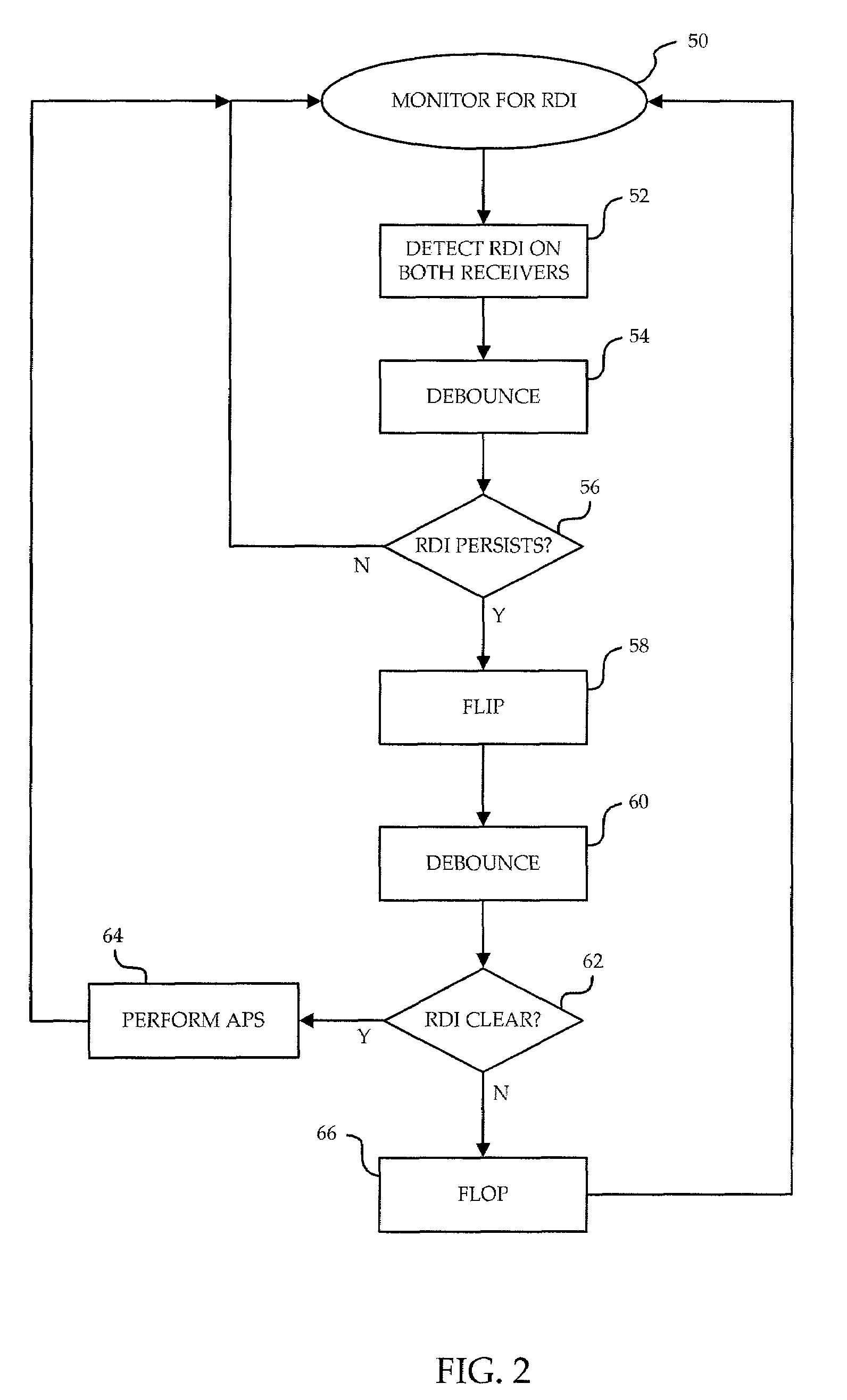
[0011]The methods and apparatus of the present invention allow defects within Y-cable communication links to be detected and potentially remedied in a short enough time that service is not significantly interrupted. By responding to RDI signals sent from the remote end upon detection of a defect in transmission by quickly switching transmitters, it may be possible to re-establish communication between the local end and the remote end in a short time, rather than hoping that a full fault will develop which may or may not be able to be corrected by higher level fault detection protocols.

Problems solved by technology

Furthermore, this failure can usually be easily pinpointed since the Rx on the active remote line card receives content over only a single path.
Since there is only one remote end line card, protection of the communication link at the remote end is impossible.
This includes failure of any component of the remote end line card, and any failure in either optical fiber on the remote end side of the Y-junction.
The difficulty lies in situation in which the local end active Tx fails or the optical fiber between the local end active Tx and the Y-junction fails.
No protocols exist for the remote end to fix such a failure.

Method used


Image

  • Method of recovery from active port tx failure in y-cable protected pair
  • Method of recovery from active port tx failure in y-cable protected pair
  • Method of recovery from active port tx failure in y-cable protected pair

Examples


Embodiment Construction

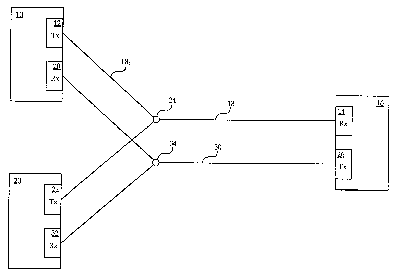
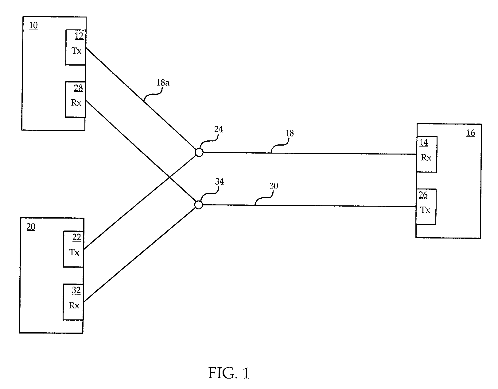
[0016]Referring to FIG. 1, a diagram of a Y-cable protected pair connection between a local end and a remote end of a communications link is shown. A first card 10 at a local end of the communication link includes a transmitter (Tx) 12 which communicates with a receiver (Rx) 14 on a second card 16 located at a remote end of the communication link. The Tx 12 communicates with the Rx 14 over a first optical fiber 18. A third card 20 at the local end includes a Tx 22 also in communication with the Rx 14 over the first optical fiber 18, although the Tx of each card at the local end connects to the first optical fiber 18 separately, at a first Y-junction 24.

[0017]The second card 16 at the remote end includes a Tx 26 which communicates with a Rx 28 on the first card 10 over a second optical fiber 30. The Tx 26 of the second card 16 also communicates with a Rx 32 on the third card 20 over the second optical fiber 30, although the Rx of each card at the local end connects to the second opti...


PUM


Abstract

A method is provided for defect recovery in Y-cable protected pair connections in communication systems. A receiver at a remote end monitors for loss of signal on the single fiber optic cable arriving at the remote end, and transmits an RDI back to the local end where it is detected by each of two receivers, one on an active card and one on a standby card. When a persistent RDI is detected by each receiver, transmission of content is flipped from the active transmitter to the standby transmitter, without performing a full APS. If RDIs are no longer received from the remote end, then the defect was likely in the single transmitter of the active card or the single optical fiber leading from the active card to the Y-junction, and the local end realizes that switching transmission to the standby card resolved the problem and a full APS is performed. The invention allows for quick recovery from defects in portions of the Y-cable communication system which may not otherwise be correctable, or even detectable, by conventional higher level fault recovery protocols.

Description

FIELD OF THE INVENTION[0001]The invention relates to fault recovery in telecommunications, and more particularly to recovery from defects in Y-cable connections.BACKGROUND OF THE INVENTION[0002]In a dual-line protected pair optical communication link, a local end and a remote end are coupled by two pairs of optical fibers. The first pair of optical fibers provides communication from a transmitter (Tx) of a first local line card to a receiver (Rx) of a first remote line card, and from a Tx of the first remote line card to a Rx of the first local line card. The second pair of optical fibers provides similar communication between a second local line card and a second remote line card. The first local line card and the first remote line card are working line cards, and the second local line card and the second remote line card are protection line cards. The working line cards are initially active cards, and the protection line cards are initially standby cards. Content is transmitted fr...

Claims


Application Information

Patent Timeline
IPC IPC(8): H04B1/38
CPCH04L1/22
Inventor MOLOTCHKO, ANDREWGRAHAM, DAVESELLARS, TERRY
Owner ALCATEL LUCENT SAS
Learn More