
Three-dimensional imaging apparatus

a three-dimensional object and imaging apparatus technology, applied in the field of three-dimensional imaging apparatuses, can solve the problems of inconvenient drawbacks of techniques, complicated implementation of barriers, and limited performance of grin lenses in non-paraxial imaging,

Inactive Publication Date: 2009-10-22
UNIV OF CONNECTICUT +1
View PDF1 Cites 33 Cited by
  • Summary
  • Abstract
  • Description
  • Claims
  • Application Information

AI Technical Summary

Problems solved by technology

However, the technical implementation of these barriers is very complicated and has been demonstrated only in the display stage and with bigger lenses (see Kim et al.
Note, however, that GRIN lenses have limited performance in non-paraxial imaging, that is, when imaging with large perspective angles.
However, this technique suffers from a number of inconvenient drawbacks.
These geometrical distortions lead to undesirable effects in the display stage, like loss of resolution or image distortions.
Additionally, the microimages are captured with poor depth of field.
Thus, out-of-focus parts of the 3D scenes are reconstructed with poor resolution.
Also, there is not any efficient way of performing dynamic focusing.
Thus, in the pickup stage it is difficult to focus the InI camera at different depths.

Method used


Image

  • Three-dimensional imaging apparatus
  • Three-dimensional imaging apparatus
  • Three-dimensional imaging apparatus

Examples


Embodiment Construction

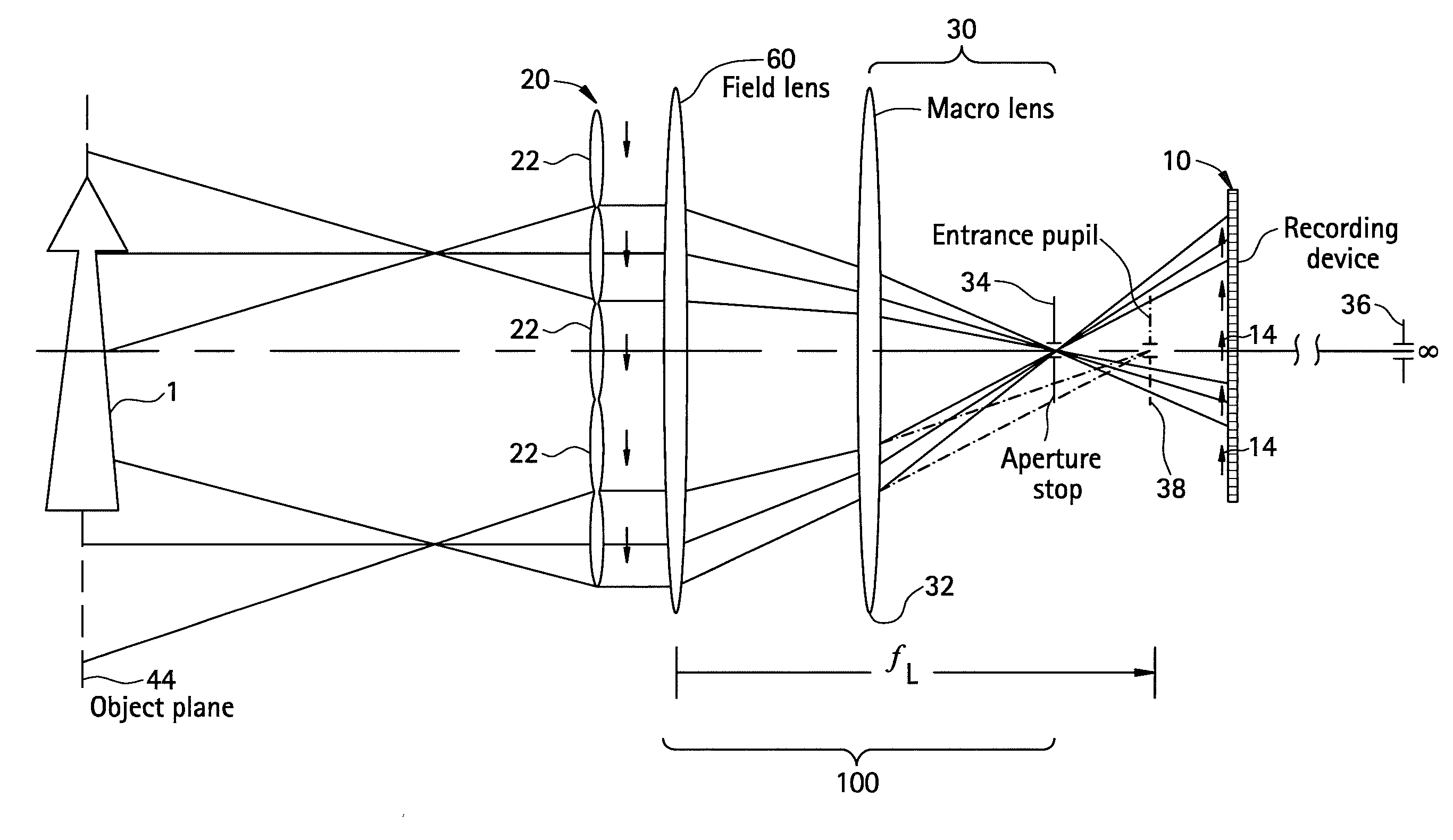
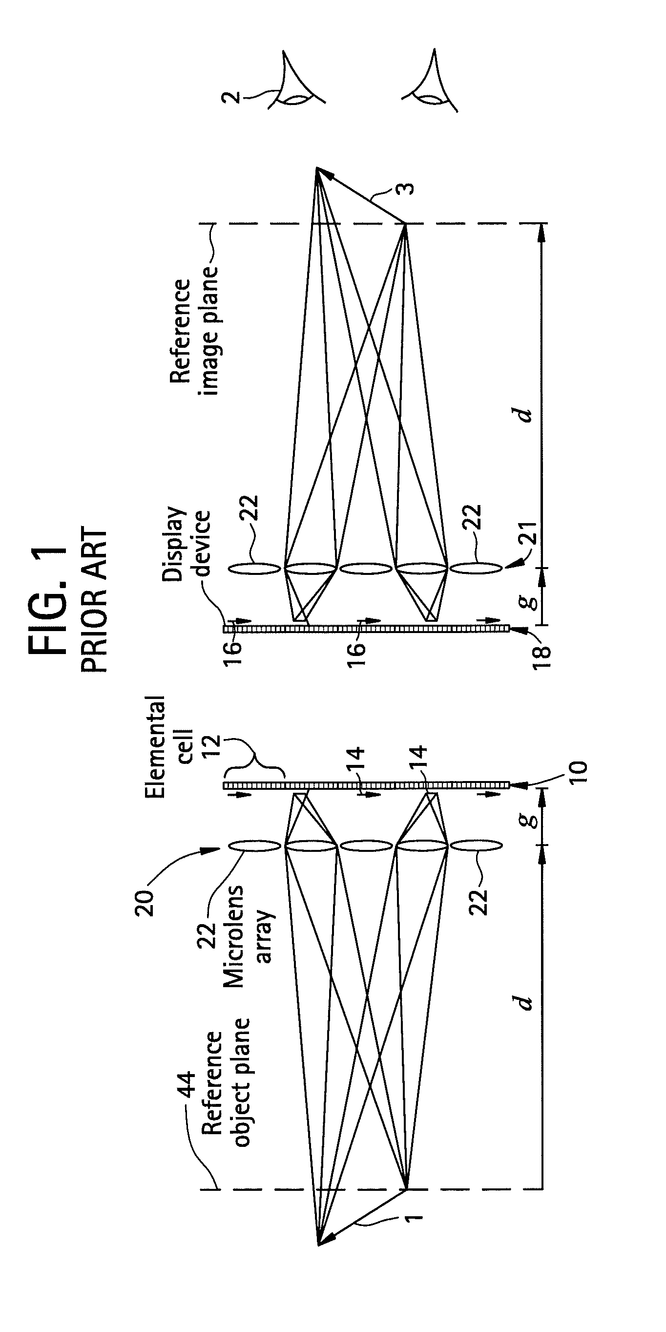
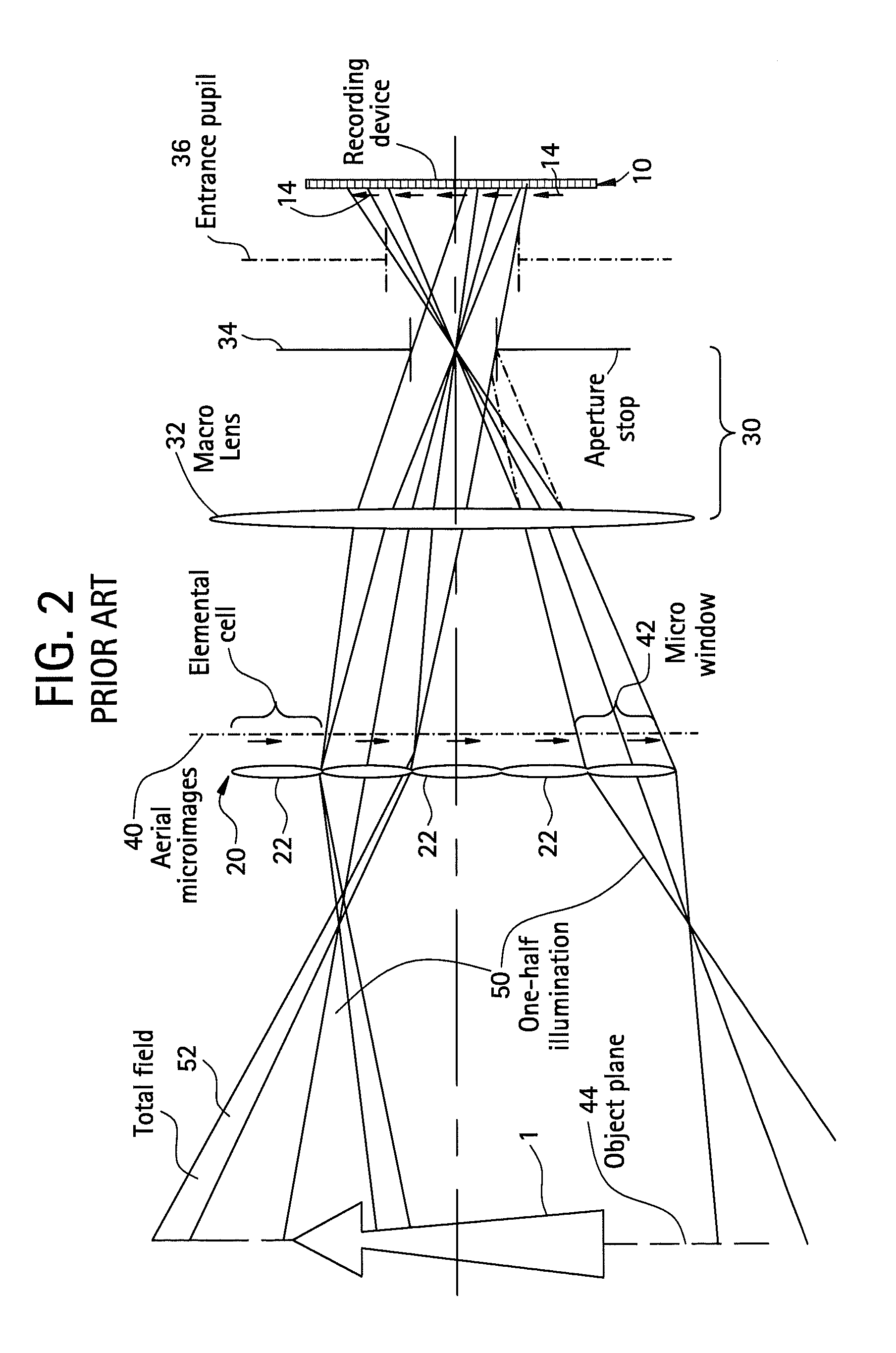
[0027]FIG. 1 shows a schematic configuration of an Integral Imaging (InI) system. As seen in FIG. 1, in the pickup stage a collection of elemental images 14, each with different perspective of the 3D scene 1, is generated onto the matrix sensor device 10. In other words, in the pickup stage of an InI system, microlens array 20 generates a collection of 2-dimensional elemental images 14 onto a matrix sensor device 10, such as a charge-coupled device (CCD), a CMOS sensor, or other appropriate device.

[0028]In the reconstruction process the recorded elemental images 16 are displayed by a matrix display device 18, such as a liquid crystal display (LCD) or other appropriate device, placed just in front of another microlens array 21. In other words, in the reconstruction stage, the set of recorded elemental images 16 are displayed in front of a second microlens array 21, providing the observer 2 with a reconstructed 3-dimensional image 3.

[0029]Although all the elemental images 16 are image...


PUM


Abstract

A three-dimensional imaging apparatus for imaging a three-dimensional object may include a microlens array, a sensor device, and a telecentric relay system positioned between the microlens array and the sensor device. A telecentric relay system may include a field lens and a macro objective that may include a macro lens and an aperture stop. A method of imaging a three-dimensional object may include providing a three-dimensional imaging apparatus including a microlens array, a sensor device, and a telecentric relay system positioned between the microlens array and the sensor device; and generating a plurality of elemental images on the sensor device, wherein each of the plurality of elemental images has a different perspective of the three-dimensional object.

Description

CROSS REFERENCE TO RELATED APPLICATIONS[0001]This application claims priority to U.S. provisional application, 60 / 980,105, filed Oct. 15, 2007, the entire contents of which are incorporated herein by reference.FIELD OF THE INVENTION[0002]At least an embodiment of the present invention may relate to devices for imaging a three-dimensional object.BACKGROUND OF THE INVENTION[0003]Three-dimensional (3D) image recording and visualization have been subjects of great interest. Among the proposed techniques Integral, Imaging (InI) provides autostereoscopic images with full parallax. Based on the principle of Integral Photography, InI has become a promising procedure to produce real-time 3D imaging (see, e.g., Okano et al., “Real time pickup method for a three-dimensional image based on internal pohotography,” Appl. Opt. 36, 1598-1603 (1997); and Arai et al. “Gradien-index lens-array method based on real-time integral photography for three-dimensional images,” Appl. Opt. 37, 2034-2045 (1998)...

Claims


Application Information

Patent Timeline
Patent Type & Authority Applications(United States)
IPC IPC(8): H04N13/02G02B13/22G02B27/12
CPCG02B3/0056H04N13/0232G02B27/2214G02B13/22
Inventor JAVIDI, BAHRAMMARTINEZ-CORRAL, MANUELMARTINEZ-CUENCA, RAULSAAVEDRA-TORTOSA, GENARO
Owner UNIV OF CONNECTICUT
Learn More