Ink jet printing apparatus

a printing apparatus and jet technology, applied in the direction of printing, other printing apparatus, etc., can solve the problems of uneven concentration of pigment, movement body damage to the inner wall of the ink cartridge, pigment settles out, etc., to achieve sufficient agitation effect, increase production cost, and not complicated structure

Inactive Publication Date: 2009-10-22
CANON KK
View PDF11 Cites 24 Cited by
  • Summary
  • Abstract
  • Description
  • Claims
  • Application Information

AI Technical Summary

Benefits of technology

[0009]An object of the present invention is to provide an ink jet printing apparatus which is not complicated in structure or does not cause an increase in production costs but is able to obtain a sufficient agitation effect without causing disadvantage such as leakage of ink.

Problems solved by technology

Further, a multi-color printer using various types of inks requires many tanks which accommodate inks according to the number of colors thereof.
The above-described printers greater in ink consumption are often provided with an ink supply source such as an ink tank at a predetermined position thereof due to the fact that it is inconvenient to move a great-capacity ink tank mounted on a carriage together with a printing head.
The pigment ink has an advantage that color develops vividly but has a fundamental disadvantage that when it is allowed to stand for a long period of time, for example, over about one to two months, the pigment settles out.
When the pigment settles out as described above, an ink inside the sub tank is made thin at the upper part of the tank and made thick at the lower part of the tank, which results in unevenness in concentrations of the pigment.
Then, this unevenness in concentrations will provide such a problem that the color of an image changes to a dark color or a light color between an initial stage of printing and a subsequent stage thereof.
However, as shown in the agitation constitution described in Japanese Patent Laid-Open No. 2003-159813, in a constitution in which a weight is used to agitate, there is a risk that a moving body may damage an inner wall of an ink cartridge on collision with the inner wall thereof.
Further, there are problems that the ink cartridge for accommodating the moving body is made more complicated in structure and constituents for the ink cartridge including the moving body are additionally required leading to an increase in production costs.
However, since a gas is filled inside the ink accommodation portion even in a state where an ink tank is not yet used, the filled air may expand with an increase in external temperatures, by which pressure inside the sub tank may increase and the ink may leak outside the tank.

Method used


Image

  • Ink jet printing apparatus
  • Ink jet printing apparatus
  • Ink jet printing apparatus

Examples


first embodiment

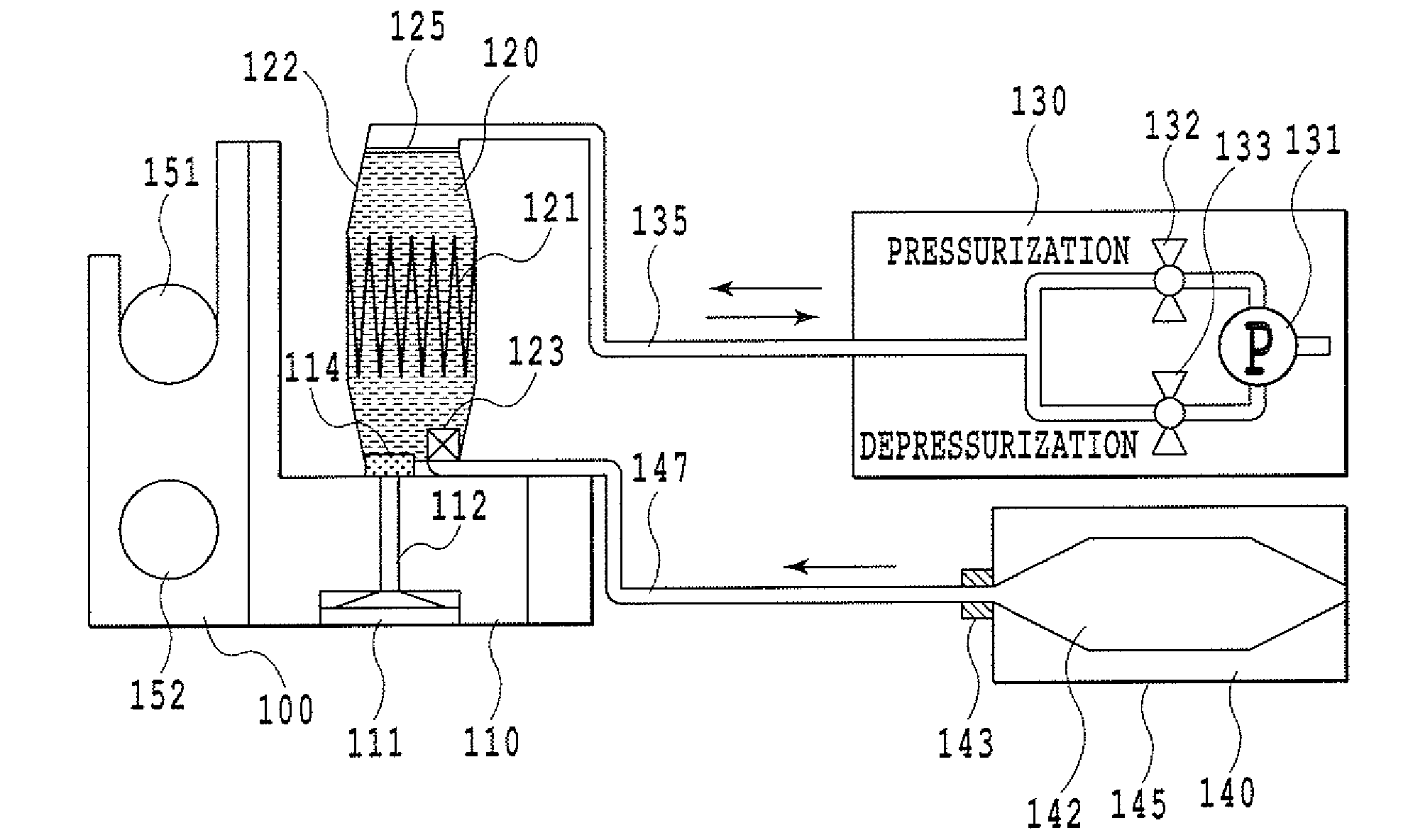
[0029]FIG. 1 is a view schematically showing an ink supply system of the ink jet printing apparatus according to a first embodiment of the present invention.

[0030]In FIG. 1, reference numeral 110 denotes a printing head for ejecting an ink, and the printing head 110 is mounted on a carriage 100. Further, a sub tank 120 is attached to the carriage 100. Then, an ink is supplied from the sub tank 120 via a filter 114 to the printing head 110. The printing head 110 is provided with a nozzle 111 for ejecting the ink and an ink flow channel 112 for supplying the ink from the sub tank to the nozzle.

[0031]Reference numeral 140 denotes a main tank, and the main tank is constituted by including a tank joint 143 connecting to an ink supply tube, an ink bag 142 for storing an ink, and a main tank case 145 for accommodating the ink bag. The ink bag 142 supplies the ink to the sub tank 120 via the tank joint 143 and the ink supply tube 147. Upon supply of the ink to the sub tank, pressure is appl...

second embodiment

[0042]FIG. 6 is a flowchart showing the processing related to an agitating operation according to a second embodiment of the present invention. With ink in an ink tank, after the elapse of a predetermined period of time, settling of pigment ink may advance. Therefore, in the present embodiment, even when no printing instruction is given to an ink jet printing apparatus, the processing proceeds to an agitating mode. Specifically, in Step 200, a determination is made for whether the predetermined time has elapsed from the time of the last performed agitating operation. When a determination is made that the predetermined time has elapsed and the pigment ink is in a state of sedimentation, the agitating operation is performed in Steps 201 to 205. Since the agitating operation of the present embodiment is the same as that of the first embodiment, the description thereof will be omitted here. After completion of the agitating operation, a determination is made for whether any printing ins...

third embodiment

[0043]FIG. 7 is a view schematically showing mainly an ink supply system of the ink jet printing apparatus according to a third embodiment of the present invention. As shown in FIG. 7, a tube pump is used as the pump in the present embodiment. Thereby, it is possible to eliminate the necessity for exchanging valves, unlike the air pump used in the above-described embodiment. Specifically, a rotating roller 138 is changed in rotating direction, thus making it possible to select the pressurization or the depressurization. In FIG. 7, the rotating roller 138 is allowed to rotate clockwise or in a direction indicated by the arrow C, by which air can be sent into the sub tank 120 via an air supply tube 135. On the other hand, when the rotating roller is allowed to rotate counterclockwise or in a direction indicated by the arrow D, air can be discharged from the sub tank 120 via the air supply tube 135.


PUM


Abstract

An air pump is driven to supply air via an air supply tube to a sub tank, by which a predetermined quantity of the air is mixed inside the sub tank via a gas-liquid separation membrane. Next, a carriage is swayed to agitate the ink by using the air mixed inside the sub tank. Then, the air pump is driven to discharge the air inside the sub tank via the gas-liquid separation membrane. In the above-described agitating motions, since the air utilized for the agitation is discharged from an ink tank after agitation processing, it is possible to prevent the air from remaining inside the ink tank to inflate, thereby adversely influencing the pressure relationship with a printing head.

Description

BACKGROUND OF THE INVENTION[0001]1. Field of the Invention[0002]The present invention relates to an ink jet printing apparatus and more particularly to a constitution for agitating an ink inside an ink tank.[0003]2. Description of the Related Art[0004]An inkjet printer, which is a typical inkjet printing apparatus, ejects an ink on a printing medium such as printing sheets to print images and characters. Among apparatuses of this type, a printer handling larger-sized printing sheets such as A0-size sheets and a professional-use printer for relatively large quantities of printing require a large-capacity ink tank in accordance with relatively large ink consumption. Further, a multi-color printer using various types of inks requires many tanks which accommodate inks according to the number of colors thereof. The above-described printers greater in ink consumption are often provided with an ink supply source such as an ink tank at a predetermined position thereof due to the fact that i...

Claims


Application Information

Patent Timeline
Patent Type & Authority Applications(United States)
IPC IPC(8): B41J29/38
CPCB41J2/17596B41J2/175
Inventor MORITA, OSAMU
Owner CANON KK
Why Eureka
Try Eureka