Transmission device, comunication system, transmission method and program

a transmission device and communication system technology, applied in the field of transmission devices, communication systems, transmission methods and programs, can solve the problems of complex circuits between transmission and reception, increase consumption power, and increase circuit size, so as to maximize the snr on the reception side and reduce the circuit size

Active Publication Date: 2009-10-15
SONY CORP
View PDF11 Cites 13 Cited by
  • Summary
  • Abstract
  • Description
  • Claims
  • Application Information

AI Technical Summary

Benefits of technology

[0007]Thus, in view of the foregoing, it is desirable to provide a transmission device, a communication system, a transmission method and a program that are new and improved, and that are capable of reducing the circuit size and maximizing the signal-to-noise power ratio (SNR) on the reception side.
[0017]According to the present invention, a transmission device, a communication system, a transmission method and a program capable of reducing the circuit size and maximizing the SNR on the reception side are provided.

Problems solved by technology

However, the MB-OFDM scheme adopts a multi-carrier system to communicate at a communication distance of about 10 m. Thus, problems arise that a circuit for transmission and reception is complicated, that circuit size grows, and also, that consumption power increases.
Further, due to the circuit design, unwanted elements such as DC cut, distortion of the frequency characteristics, and the like, may be included in the transmission and reception sides, and the need arises to compensate for the degradation in an analog domain of the transmission side and the reception side connected through a wireless channel.

Method used


Image

  • Transmission device, comunication system, transmission method and program
  • Transmission device, comunication system, transmission method and program
  • Transmission device, comunication system, transmission method and program

Examples


Embodiment Construction

[0044]Hereinafter, preferred embodiments of the present invention will be described in detail with reference to the appended drawings. Note that, in this specification and the appended drawings, structural elements that have substantially the same function and structure are denoted with the same reference numerals, and repeated explanation of these structural elements is omitted.

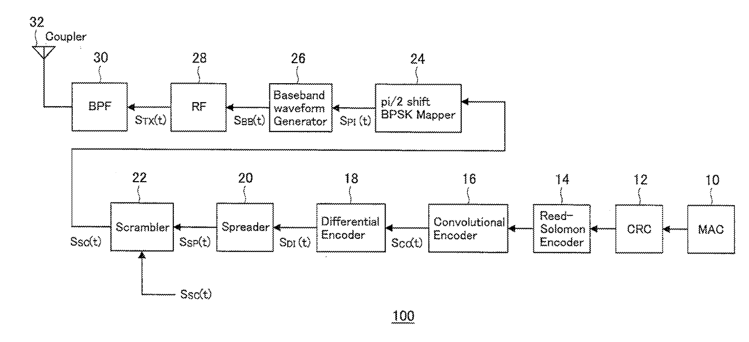
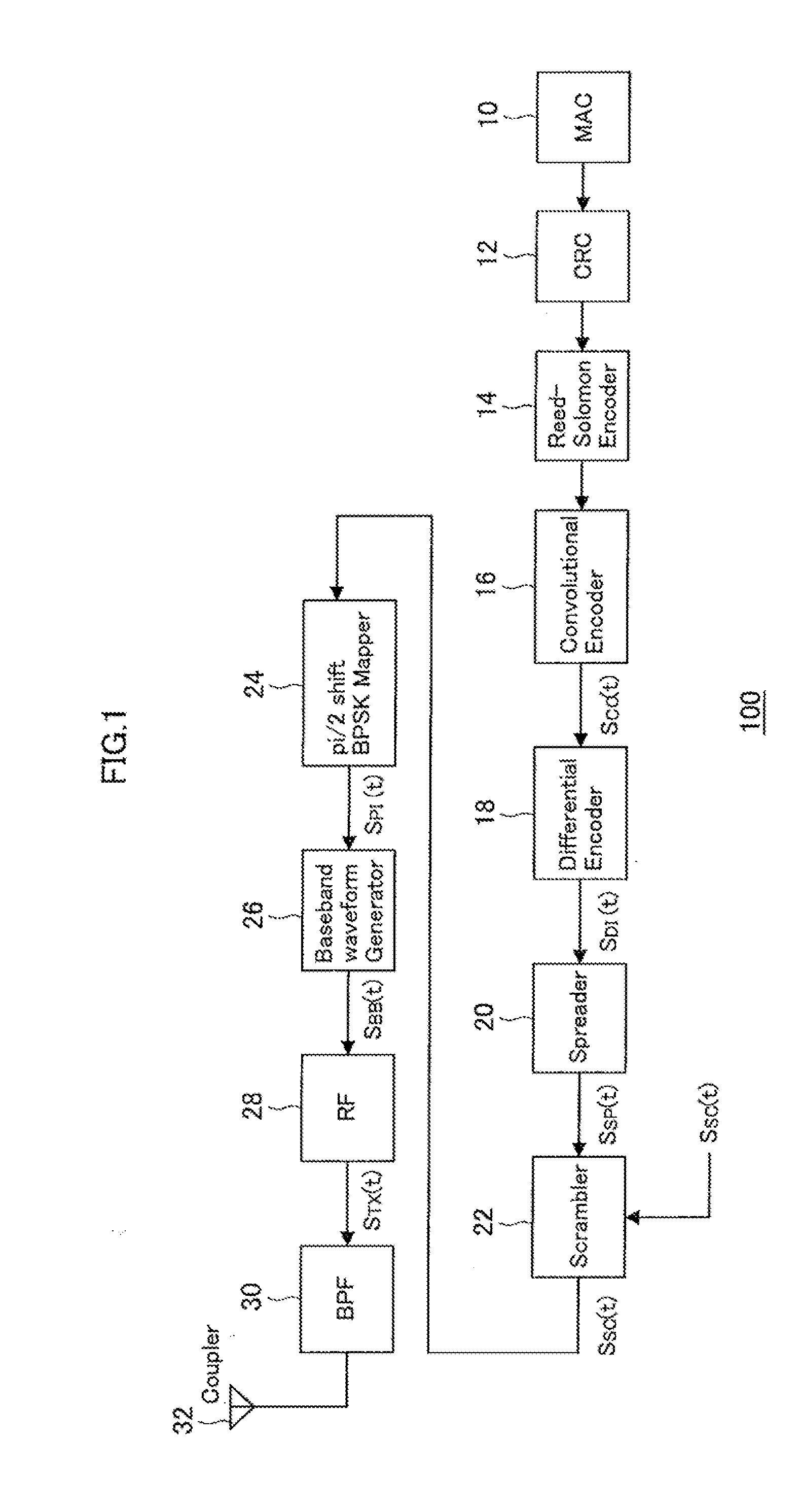
[0045]FIG. 1 is a schematic diagram showing a configuration of a wireless transmission device 100 according to an embodiment of the present invention. As shown in FIG. 1, the wireless transmission device 100 of the present embodiment includes a media access control (MAC) 10, a cyclic redundancy check (CRC) 12, a Reed-Solomon encoder 14, a convolutional (Viterbi) encoder 16, a differential encoder 18, a spreader 20, a scrambler 22, a Pi / 2 shift BPSK mapper 24, a baseband waveform generator 26, an RF circuit 28, a band pass filter (BPF) 30 and an antenna 32. The wireless transmission device 100 transmits data ...


PUM


Abstract

A transmission device of the present, invention includes a baseband waveform generator to generate a transmission signal by using a transfer function H0(f) that is in a relation of a matched filter with a transfer function H1(f) in an analog domain of a transmission side and a reception side connected through a wireless channel, and transmits the transmission signal generated fay the baseband waveform generator.

Description

BACKGROUND OF THE INVENTION[0001]1. Field of the Invention[0002]The present invention relates to a transmission device, a communication system, a transmission method and a program,[0003]2. Description of the Related Art[0004]In the past, a short range communication system, such as a MB-OFDM scheme adopted fay a wireless USB, having a distance of about 10 m in view has been proposed.[0005][Patent Document 1] JP-A-2005-253102SUMMARY OF THE INVENTION[0006]However, the MB-OFDM scheme adopts a multi-carrier system to communicate at a communication distance of about 10 m. Thus, problems arise that a circuit for transmission and reception is complicated, that circuit size grows, and also, that consumption power increases. Further, due to the circuit design, unwanted elements such as DC cut, distortion of the frequency characteristics, and the like, may be included in the transmission and reception sides, and the need arises to compensate for the degradation in an analog domain of the trans...

Claims


Application Information

Patent Timeline
Patent Type & Authority Applications(United States)
IPC IPC(8): H04B1/707H04L27/00H04L27/20H04B1/713H04J11/00H04J13/10H04J13/16H04L27/18
CPCH04L25/08H04L25/03
Inventor WATANABE, KATSUMI
Owner SONY CORP
Why Eureka
Try Eureka