Digital signal input device and method of controlling the same
a digital signal and input circuit technology, applied in pulse manipulation, pulse duration/width modulation, pulse technique, etc., can solve problems such as inability to deal with problems, difficult to achieve the effect of input circuits of the same configuration, and large amount of heat generated
- Summary
- Abstract
- Description
- Claims
- Application Information
AI Technical Summary
Benefits of technology
Problems solved by technology
Method used
Image

Examples
first embodiment
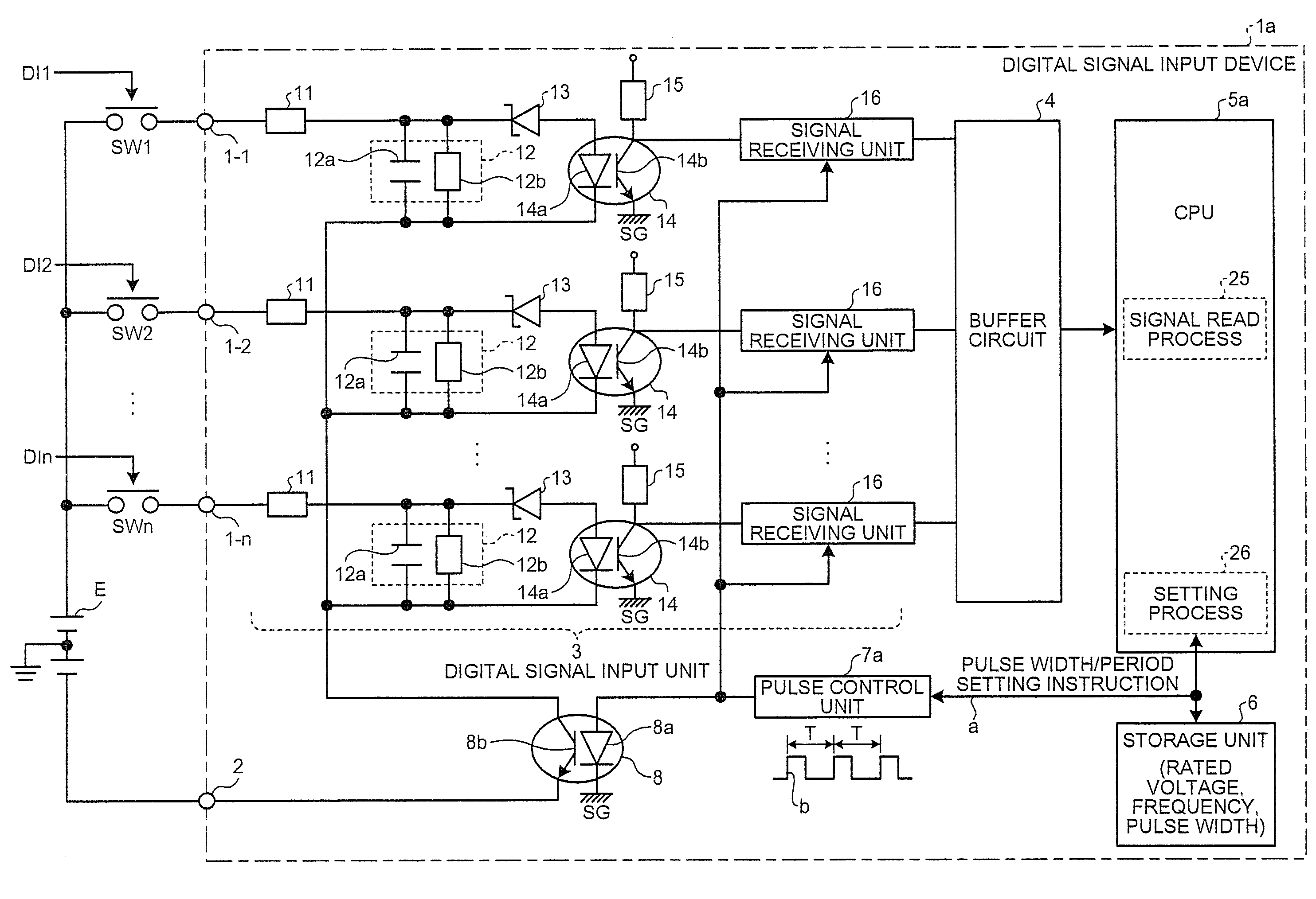
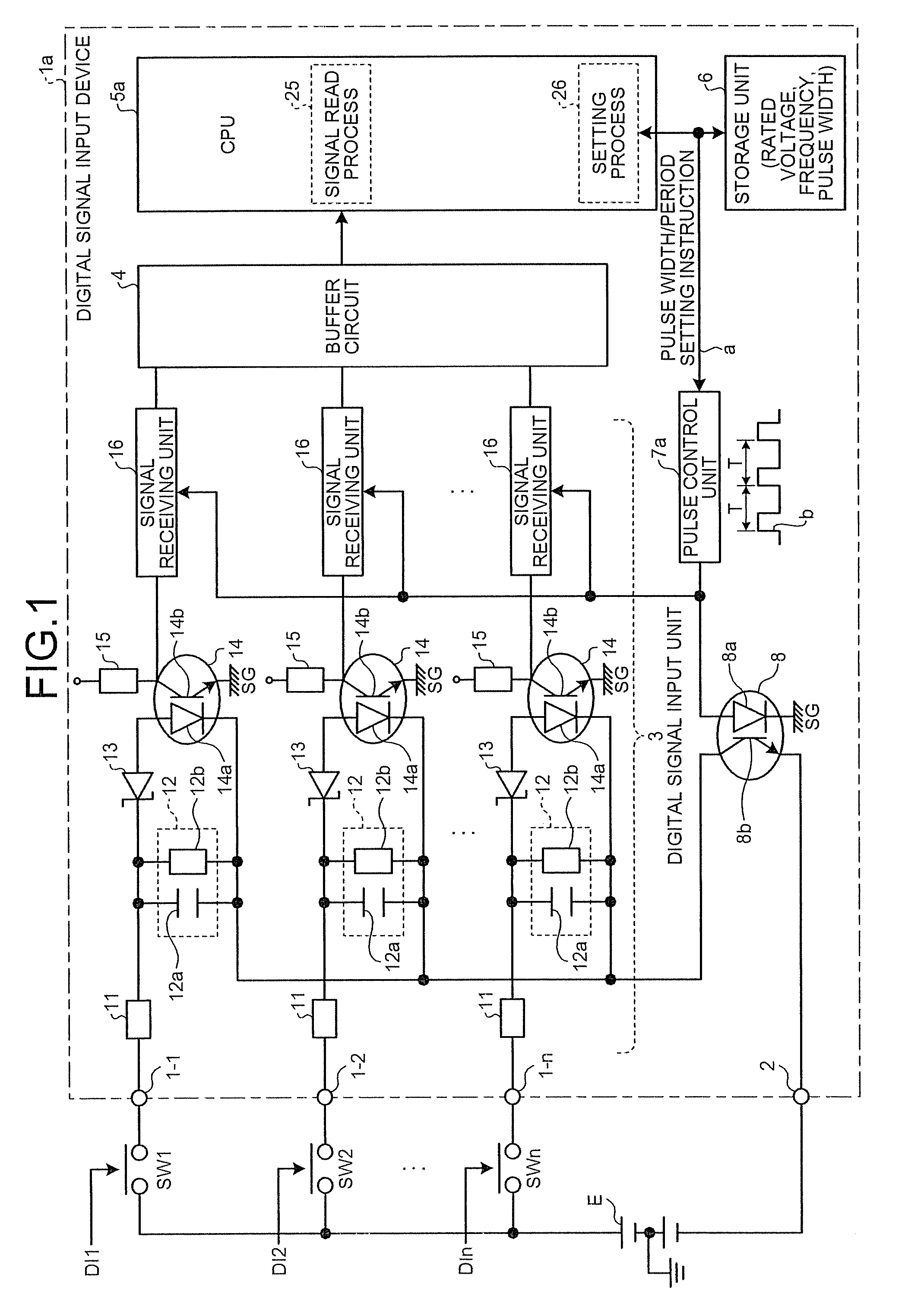
[0042]FIG. 1 is a block diagram of a digital signal input device 1a according to the present invention.
[0043]In FIG. 1, a direct-current (DC) power supply E and switches SW1 to SWn are not provided at the digital signal input device 1a, but rather are provided at the actual location where the digital signal input device 1a is provided (in this case, an electrical station such as a transformer station).
[0044]The DC power supply E is a DC controlling power supply provided at an electrical station such as a transformer station. Various voltages such as DC 48 volts, DC 110 volts, or DC 220 volts can be used as the voltage for the DC power supply E. The voltage of the DC power supply E does not have to be the same at all electrical stations but rather can be different depending on the electrical station. As depicted in FIG. 1, there are also cases where the DC power supply E is installed with an earth connection provided at a central point of two power supplies connected in series to ens...
second embodiment
[0096]As shown in FIG. 6, a digital signal input device 1b of the second embodiment is the configuration shown in FIG. 1 (the first embodiment) with a CPU 5b provided in place of the CPU 5a and with a pulse control unit 7b provided in place of the pulse control unit 7a. A time constant determination process 27 is added at the CPU 5b.
[0097]In the first embodiment, the case where the rated voltage and the pulse width and pulse period for the rated voltage are stored in advance in the storage unit 6 is shown. However, in the second embodiment, the case is shown where this device is actually made to operate under an arbitrary predetermined rated voltage applied across an arbitrary first input terminal and second input terminal 2. The time constant determination process 27 then determines the time constant from the pulse width obtained at this time and decides the input rated voltage. The decided rated voltage is then stored in the storage unit 6 together with the pulse width. The CPU 5...
third embodiment
[0108]As shown in FIG. 9, a digital signal input device 1c of the third embodiment is the configuration shown in FIG. 1 (the first embodiment) with a CPU 5c provided in place of the CPU 5a and with a pulse control unit 7c provided in place of the pulse control unit 7a. A pulse width adjustment process 28 is added at the CPU 5c.
[0109]The third embodiment demonstrates countermeasures for adjusting pulse width with respect to individual errors of the capacitor 12a and the resistor 12b constituting the current-limiting resistor 11 and the CR filter 12 and with respect to fluctuations in detection level due to changes over time in the Zener diode 13 and the insulating photocoupler 14.
[0110]In addition to the normal operating mode, the CPU 5c includes a pulse width adjustment mode for adjusting the pulse width prior to shipping of the product. The pulse width adjustment process 28 is executed during the pulse width adjustment mode.
[0111]The pulse control unit 7c adjusts the pulse width o...
PUM
 Abstract
Description
Claims
Application Information
 - R&D
- Intellectual Property
- Life Sciences
- Materials
- Tech Scout
- Unparalleled Data Quality
- Higher Quality Content
- 60% Fewer Hallucinations
Browse by: Latest US Patents, China's latest patents, Technical Efficacy Thesaurus, Application Domain, Technology Topic, Popular Technical Reports.
© 2025 PatSnap. All rights reserved.Legal|Privacy policy|Modern Slavery Act Transparency Statement|Sitemap|About US| Contact US: help@patsnap.com