
Solar parametric testing module and processes

a solar cell and parametric testing technology, applied in the field of apparatus and processes for testing and analyzing the properties of solar cell devices, can solve the problems of high labor intensity of conventional solar cell manufacturing processes, affecting the yield of solar cells, and affecting the throughput of production lines,

Inactive Publication Date: 2009-10-15
APPLIED MATERIALS INC
View PDF19 Cites 38 Cited by
  • Summary
  • Abstract
  • Description
  • Claims
  • Application Information

AI Technical Summary

Benefits of technology

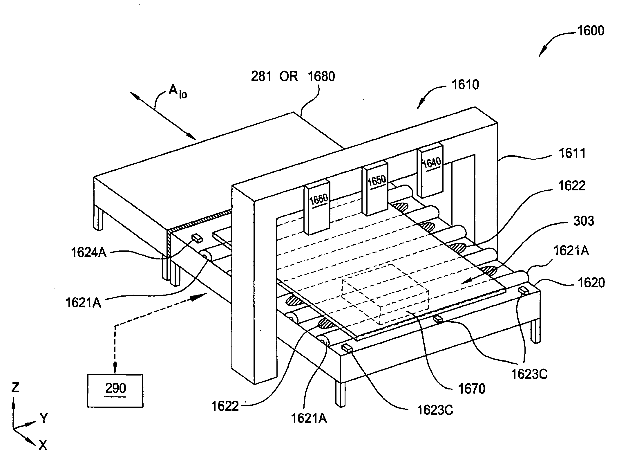
[0010]In one embodiment of the present invention, a solar parametric testing module comprises an automation system having a conveyor configured to receive a solar cell substrate having one or more test structures formed thereon into the solar parametric testing module and transfer the solar cell substrate out of the solar parametric testing module, a vision system having one or more cameras, and a measurement module configured to supply a voltage to a plurality of points on the one or more test structures and measure the resistance between the points. In one embodiment, the vision system is configured to scan the solar cell substrate and send signals regarding the position of one or more features on the solar cell substrate to a system controller. In one embodiment, the automation system is further configured to receive commands from the system controller and position the solar cell substrate based on the signals sent by the vision system.
[0011]In another embodiment, a solar parametric testing module comprises an automation system having a conveyor configured to receive a solar cell substrate having one or more test structures formed thereon into the solar parametric testing module and transfer the solar cell substrate out of the solar parametric testing module, a vision system having one or more cameras, a measurement module configured to supply a voltage to a plurality of points on the one or more test structures and measure the resistance between the points, a light source configured to project a controlled amount of light toward a surface of the one or more test structures on a side opposite the measurement module, and an efficiency module coupled to the resistance measurement module and the light source and configured to characterize the performance of the one or more test structures via the light source and the measurement module. In one embodiment, the vision system is configured to scan the solar cell substrate and send signals regarding the position of one or more features on the solar cell substrate to a system controller. In one embodiment, the automation system is further configured to receive commands from the system controller and position the solar cell substrate based on the signals sent by the vision system.
[0012]In yet another embodiment of the present invention, a method of characterizing electrical characteristics of a solar cell comprises receiving a solar cell substrate having one or more test structures formed thereon onto an automation system of a solar parametric testing module, sensing the position of the solar cell substrate on the automation system, horizontally positioning the solar cell substrate with respect to at least one edge of the solar cell substrate, locating at least one feature of the solar cell substrate via a vision system comprising at least one camera, sending a signal from the vision system to a system controller, grasping the solar cell substrate with a gripping element and refining the position of the solar cell substrate based on the signal sent by the vision system, contacting the one or more test structures of the solar cell substrate with a plurality of probe pins, measuring electrical characteristics of the one or more test structures via a measurement module coupled to the probe pins, and transferring the solar cell substrate out of the solar parametric testing module.

Problems solved by technology

Conventional solar cell manufacturing processes are highly labor intensive and have numerous interruptions that can affect production line throughput, solar cell cost, and device yield.

Method used


Image

  • Solar parametric testing module and processes
  • Solar parametric testing module and processes
  • Solar parametric testing module and processes

Examples


Embodiment Construction

[0039]Embodiments of the present invention generally relate to a module that can test and analyze various regions of a solar cell device in an automated or manual fashion after one or more steps have been completed in the solar cell formation process. While the discussion below primarily describes the formation of a silicon thin film solar cell device, this configuration is not intended to be limiting to the scope of the invention since the apparatus and methods disclosed herein could be used to test and analyze other types of solar cell devices formed from materials, such as III-V type solar cells, thin film chalcogenide solar cells (e.g., CIGS, CdTe cells), amorphous or nanocrystalline silicon solar cells, photochemical type solar cells (e.g., dye sensitized), crystalline silicon solar cells, organic type solar cells or other similar solar cell devices. The module used to perform the automated testing and analysis processes can also be adapted to test a partially formed solar cell...


PUM

PropertyMeasurementUnit
sizeaaaaaaaaaa
temperatureaaaaaaaaaa
wavelengthaaaaaaaaaa

Abstract

Embodiments of the present invention generally relate to a module that can test and analyze various regions of a solar cell device in an automated or manual fashion after one or more steps have been completed in the solar cell formation process. The module used to perform the automated testing and analysis processes can also be adapted to test a partially formed solar cell at various stages of the solar cell formation process within an automated solar cell production line. The automated solar cell production line is generally an arrangement of automated processing modules and automation equipment that is used to form solar cell devices.

Description

CROSS-REFERENCE TO RELATED APPLICATIONS[0001]This application claims benefit of U.S. provisional patent application Ser. No. 61 / 044,852, filed Apr. 14, 2008, which is herein incorporated by reference.[0002]This application is related to U.S. application Ser. No. 12 / 202,199, filed Aug. 29, 2008 and U.S. application Ser. No. 12 / 201,840, filed Aug. 29, 2008.BACKGROUND OF THE INVENTION[0003]1. Field of the Invention[0004]Embodiments of the present invention generally relate to apparatus and processes for testing and analyzing the properties of a solar cell device at various stages of formation.[0005]2. Description of the Related Art[0006]Photovoltaic (PV) devices or solar cells are devices which convert sunlight into direct current (DC) electrical power. Typical thin film type PV devices, or thin film solar cells, have one or more p-i-n junctions. Each p-i-n junction comprises a p-type layer, an intrinsic type layer, and an n-type layer. When the p-i-n junction of the solar cell is expo...

Claims


Application Information

Patent Timeline
Patent Type & Authority Applications(United States)
IPC IPC(8): G01R27/08B65G47/00H01L21/683
CPCH01L21/67253H02S50/10H01L21/681Y02E10/50
Inventor LU, DANNY CAM TOANMARRIOTT, MICHAELSVIDENKO, VICKYWANG, DAPENGFREI, MICHEL R.
Owner APPLIED MATERIALS INC
Learn More