
Electrode introducer device

a technology of introducer device and electrode, which is applied in the field of introducer device of electrode, can solve the problems of difficult access to the sub-surface and inability to achieve the effect of introducing the electrode under such conditions as is not possibl

Inactive Publication Date: 2009-10-08
REGION HOVEDSTADEN VHERLEV HOSPITAL
View PDF31 Cites 32 Cited by
  • Summary
  • Abstract
  • Description
  • Claims
  • Application Information

AI Technical Summary

Benefits of technology

"The present invention provides an electroporation device and method that overcomes the shortcomings of existing devices. The device has an improved design that allows for deeper-lying or difficult-to-access regions of the body to be accessed with minimal damage to the surrounding tissue. The device can deliver an efficient and flexible electric field to enhance the transfer of therapeutical molecules or other substances through cell membranes. The device has a small outer extent, which reduces the risk of injury to the tissue. The electrodes can be individually controlled to provide a more flexible and efficient electrical field. The device can also be used in combination with other devices to create a more complex and targeted electric field. Overall, the device provides a safer and more effective tool for electroporation therapy."

Problems solved by technology

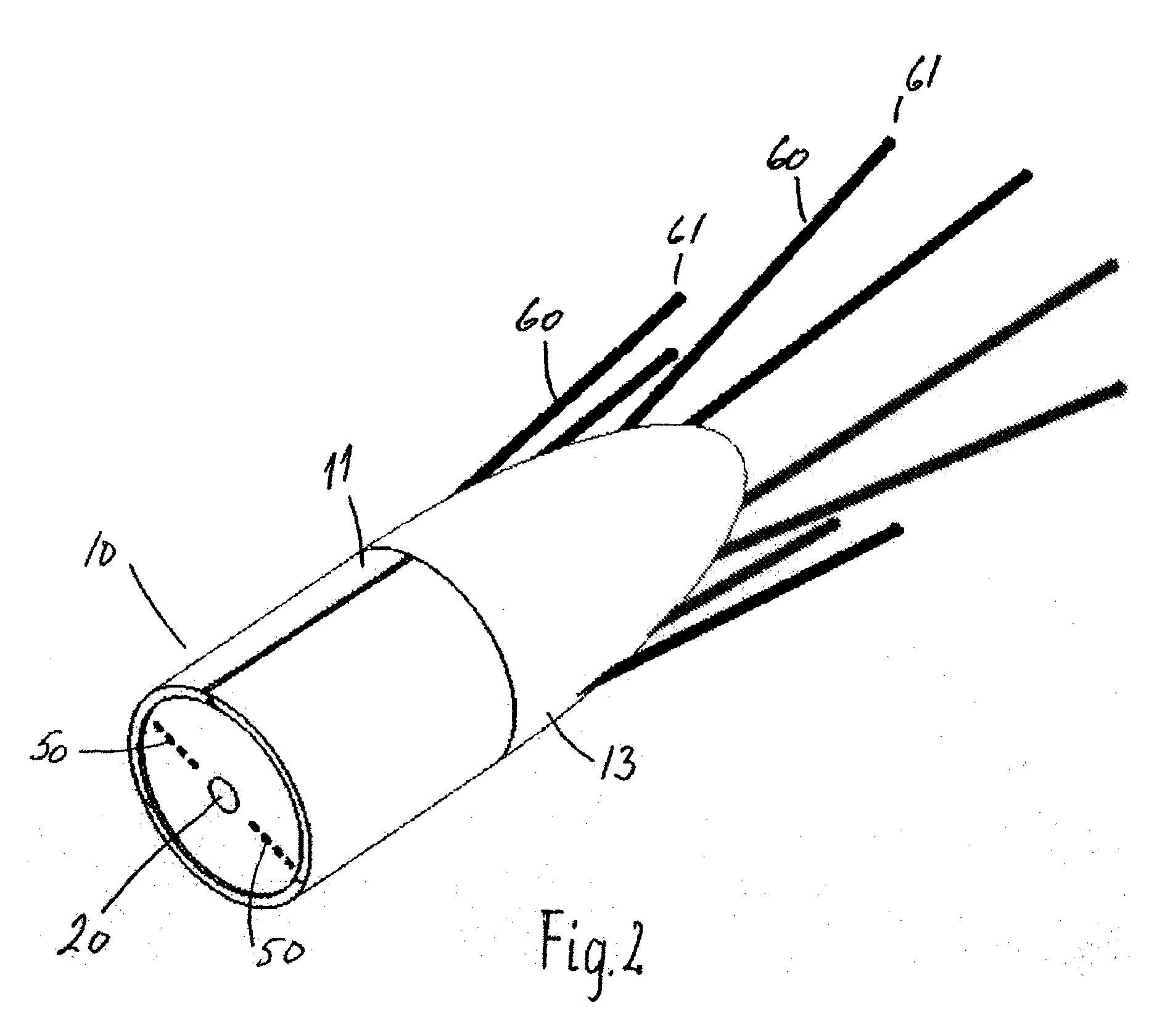
Furthermore, this can be obtained under such sub-surface circumstances (deeper-lying / difficultly accessible regions) as is not possible with prior art devices, through the sub-surface deployment of multiple electrodes that are angled away from the introducer shaft and comprise respective un-insulated end-points, preferably placed in an equidistant relationship, that may circumscribe the outer periphery of such an ellipsoid or other geometric shape in the target region.

Method used


Image

  • Electrode introducer device
  • Electrode introducer device
  • Electrode introducer device

Examples


Embodiment Construction

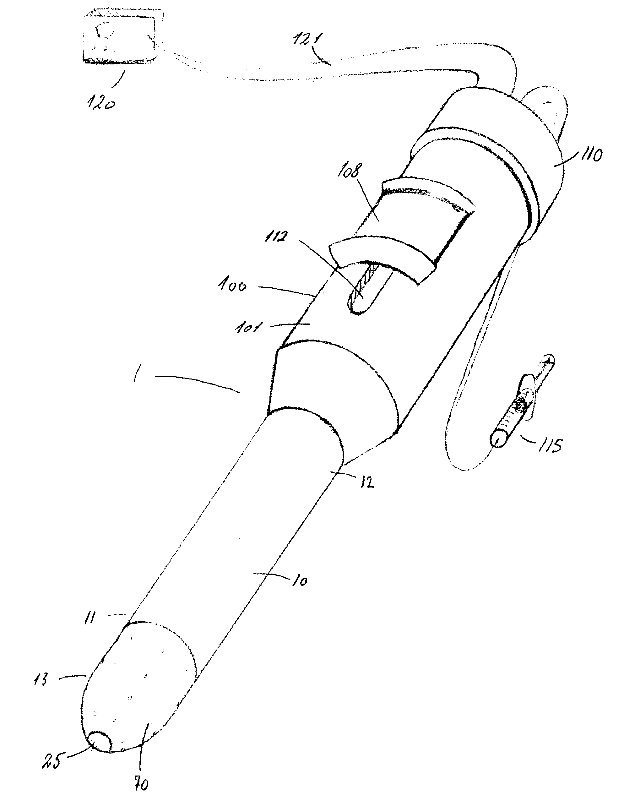
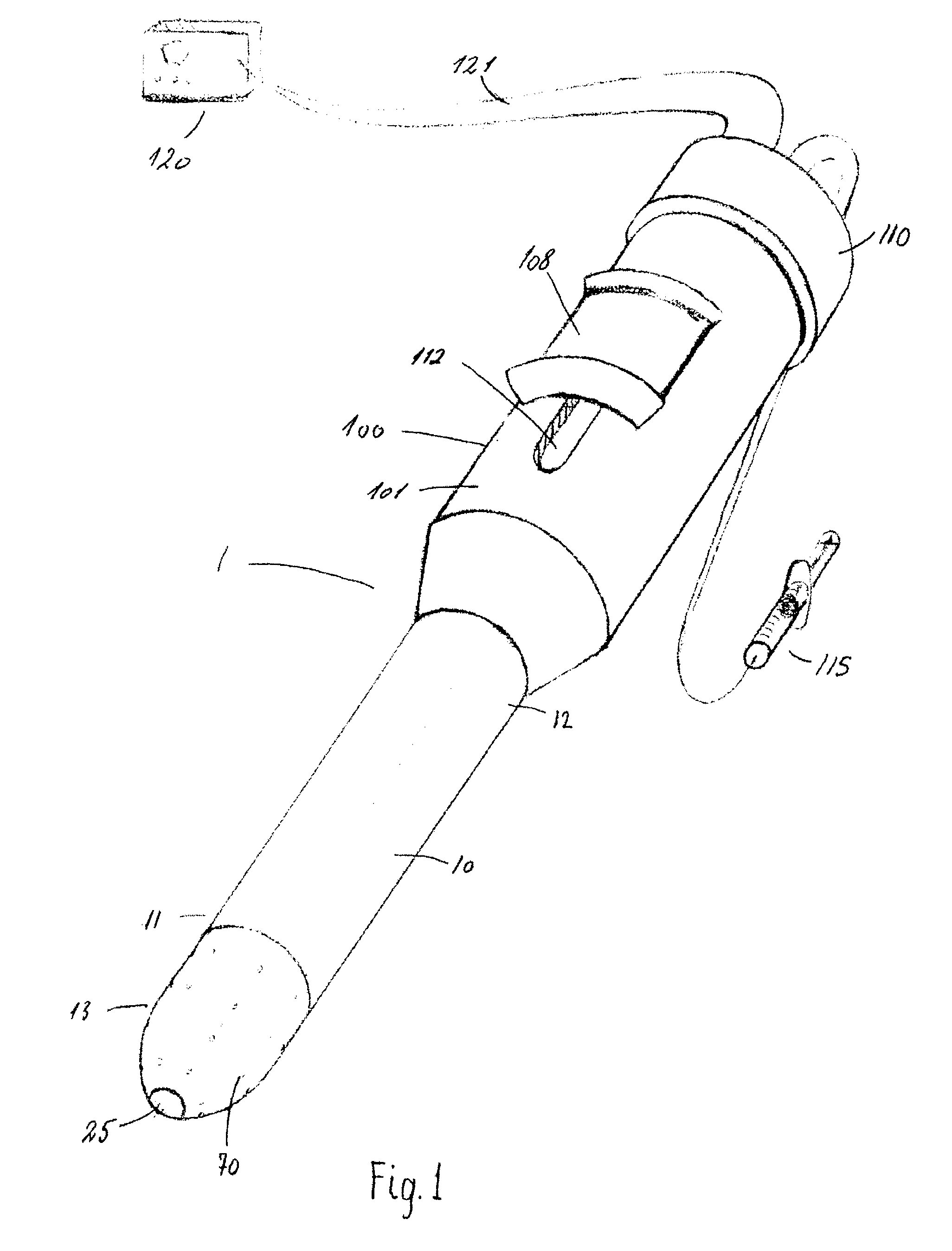
[0050]In FIG. 1 an electrode introducing electroporation device 1 according to an embodiment of the invention is shown. The device 1 comprises a handle section 100 and an elongate introducer shaft 10 preferably having a length suitable for accessing deeper-lying tissue regions. The length of the shaft 10 may be adapted for the intended use. The shaft 10 is attached to the handle section 100, and has a proximal end 12 adjacent to the handle section 100 and a distal end 11. The shaft may in one embodiment be fixedly attached to the handle section. In other embodiments the shaft may be detachably mounted to the handle section 100, and may comprise suitable means for establishing temporary connections, e.g. for conducting electrical pulses. A distal tip 13, that is preferably shaped to permit the creation of a channel through intervening layers of tissue while causing minimal damage to said tissue, is disposed at the distal end 11 of said shaft 10. The distal tip 13 has a rounded, non-c...


PUM


Abstract

An electroporation device 1 comprising a handle section 100; an elongate introducer shaft 10 connected to said handle section 100, said introducer shaft 10 having a distal tip 13; and a set of electrodes 60 having respective distal ends 61, each electrode 60 being slidably arranged within said introducer shaft 10 from a retracted position, where said distal ends 61 are enclosed within said introducer shaft 10, to an exposed position, where said distal ends 61 extend from said distal tip 13; wherein said electrode distal ends 61 are deflectable away from a longitudinal axis L of said shaft 10 when deployed / extended to their extended position, such that at least one planar projection taken in a plane perpendicular to said longitudinal axis L of distance D1 between a pair of distal ends 61 of said electrodes 60 is larger than a maximal extent D2 of a cross-section of said introducer shaft 10, said cross-section taken in a plane perpendicular to said longitudinal axis L at a distal end 11 of said introducer shaft 10.

Description

[0001]The present invention concerns a device and a method for electroporation, in general and more specifically the present invention concerns a device and method for administering therapeutical molecules, such as a drug, an isotope or genetic material enhanced by electric pulses causing electroporation of and / or electrophoretic effects in a target region of a patient's body.BACKGROUND OF THE INVENTION[0002]In the treatment of diseases in the brain, e.g. brain cancer, as well as diseases in other anatomical areas of a body, physical access to a diseased tissue region may be a challenge. This is especially the case if the diseased region lies deep within the body of the patient. Furthermore, efficient delivery and subsequent uptake of therapeutic molecules, such as a drug or genetic compound, to an anatomical target tissue is often a problem.[0003]Electroporation is a known method used to deliver drugs and genetic material to various biologic tissues, where the uptake of these subst...

Claims


Application Information

Patent Timeline
Patent Type & Authority Applications(United States)
IPC IPC(8): A61N1/30
CPCA61B18/1477A61B2017/00867A61B2018/00083A61B2018/143C08L2201/12A61B2018/1495A61B2218/002A61N1/05A61N1/327A61B2018/1475A61B2018/00613A61N1/0502
Inventor GEHL, KAREN JULIEVIDEBAEK, KARSTEN
Owner REGION HOVEDSTADEN VHERLEV HOSPITAL
Learn More