Drive device using charged air pressure

a technology of driving device and charged air, which is applied in the direction of fluid coupling, servomotor, coupling, etc., to achieve the effect of strong output and high energy

Inactive Publication Date: 2009-10-08
MURAKAMI EIZABURO +2
View PDF1 Cites 6 Cited by
  • Summary
  • Abstract
  • Description
  • Claims
  • Application Information

AI Technical Summary

Benefits of technology

[0015]Moreover, as for the sustainability, it is impossible to completely prevent the fill pressure air from leaking from the cylinder, and therefore it is necessary to replenish the cylinder chamber with air pressure to fill it therewith. This makes it extremely difficult to obtain a stroke for a long time with no exhaust stroke at the time of alternate up-and-down movements of the right and left pistons.
[0036]According to the invention recited in claim 9, the piston-rods of the air-filled cylinders, by moving them up and down, perform up-and-down movements of the pistons and the opening and closing of the intake and exhaust valves associated with these movements, and, since they are coupled to an input section such as a motor through the mediation of a gear mechanism producing a boosted force proportional to the main wheel diameter and the diameter of a pinion, it is possible to reliably move the piston rods up and down without using much force.

Problems solved by technology

However, Patent Document 1 described above drives the switching gear rotated by a small external force so as to rotate in a reciprocating manner, alternately repeating left rotation and right rotation, to move first and second rack members in parallel in opposite directions, one leftward, the other rightward, and is unfit for rotation in a particular direction, for example, input by stepping on a pedal of a bicycle or the like, input with a battery-driven small motor, or input by rotating a crank by hand in one direction.

Method used


Image

  • Drive device using charged air pressure
  • Drive device using charged air pressure
  • Drive device using charged air pressure

Examples


Embodiment Construction

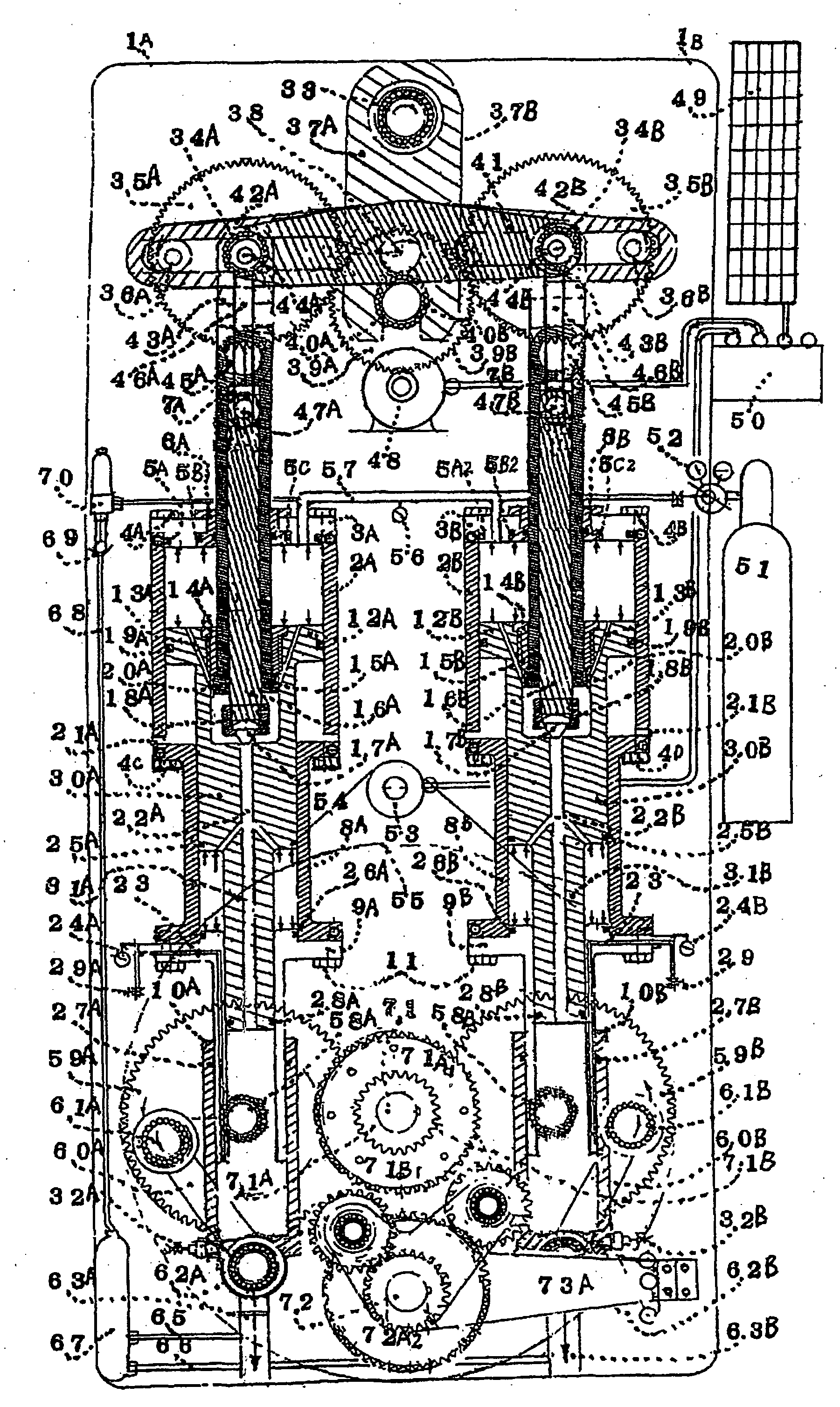
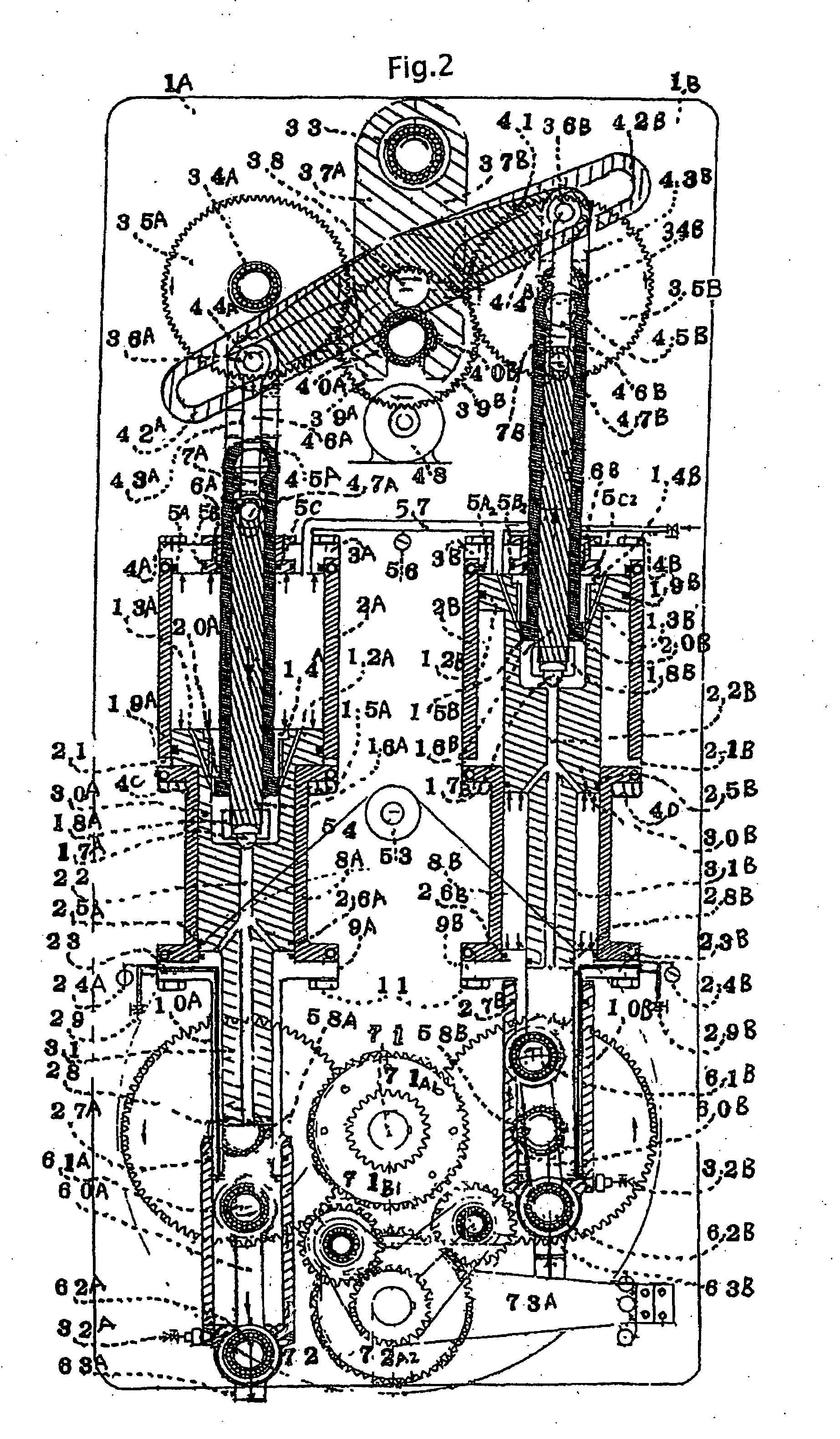
[0056]Hereinafter, embodiments of the present invention will be explained in detail with reference to the drawings. FIG. 1 is an explanatory diagram showing a first embodiment of a drive device using filled air according to the invention. In this figure, 1A and 1B denote frames for fixing a cylinder.

[0057]The drive device using filled air according to the invention is basically a drive device using charged air pressure, the drive device including a cylinder device in which two air pressure filled cylinders are communicated with each other, pistons of the cylinders are pressurized under the same pressure by compressed air fed to each cylinder, and piston rods of the pistons are made to reciprocate alternately by an external input device, an external input device feeding an external input to it, and a rotation output extracting mechanism that makes the pistons of the cylinders reciprocate alternately and obtains torque by this reciprocating movement.

[0058]First, the cylinder device is...


PUM


Abstract

In a drive device, two cylinders filled with air pressure are interconnected, and the pistons of the cylinders are pressed under the same pressure by compressed air supplied to the cylinders. The drive device has an external input device for applying an external input to the cylinders so that the pistons reciprocate alternately. The external input device causes the pistons to reciprocate alternately, and the reciprocation motion provides rotational force. The interconnected cylinders are multi-stage cylinders, pressurized air flow paths (22A, 22B) connected to each cylinder stage are formed in the multi-stage cylinders, and (17A, 17B) for opening and closing the flow paths are also provided in the cylinders.

Description

TECHNICAL FIELD[0001]The present invention relates to a drive device using a filled air pressure as the one that can be driven without using a drop of gasoline fuel or the like for prevention of environmental pollution, the drive device that can extract doubled output that is proportional to fill pressure to the outside by compressing and filling air serving as natural energy, is effective in saving energy and maintaining environmental health, and is in particular suitable for use as a drive source of a pollution-free drive device in various drive devices including travel devices, such as bicycles and automobiles, and generators.BACKGROUND ART[0002]The applicant previously filed a pressure-mechanical converting device, which converts air pressure into mechanical power by the patent document mentioned below, and obtained a patent right.[0003](Patent Document 1) Japanese Patent No. 2127336[0004]This uses compressed gas at a specified pressure as a drive source, and uses a set of opera...

Claims


Application Information

Patent Timeline
Patent Type & Authority Applications(United States)
IPC IPC(8): F15B11/17
CPCB62M2007/005F01B5/00F01B7/18F01B9/08F01B9/023F01B9/042F01B7/20
Inventor MURAKAMI, EIZABUROMURAKAMI, NOBORUMURAKAMI, SATOSHI
Owner MURAKAMI EIZABURO
Why Eureka
Try Eureka