
Acoustic echo canceler

a canceler and acoustic technology, applied in the field of acoustic echo cancelers, can solve the problems of difficult to perform echo cancellation appropriately, difficult to communicate with auditors, and inconvenience for talkers, and achieve the effect of reducing the error of double-talk detection and simple constitution

Active Publication Date: 2009-10-01
YAMAHA CORP
View PDF1 Cites 23 Cited by
  • Summary
  • Abstract
  • Description
  • Claims
  • Application Information

AI Technical Summary

Benefits of technology

[0018]It is an object of the present invention to provide an acoustic echo canceler which performs high-precision echo cancellation with a simple constitution and without erroneous detection of a user's speech in a double-talk event.
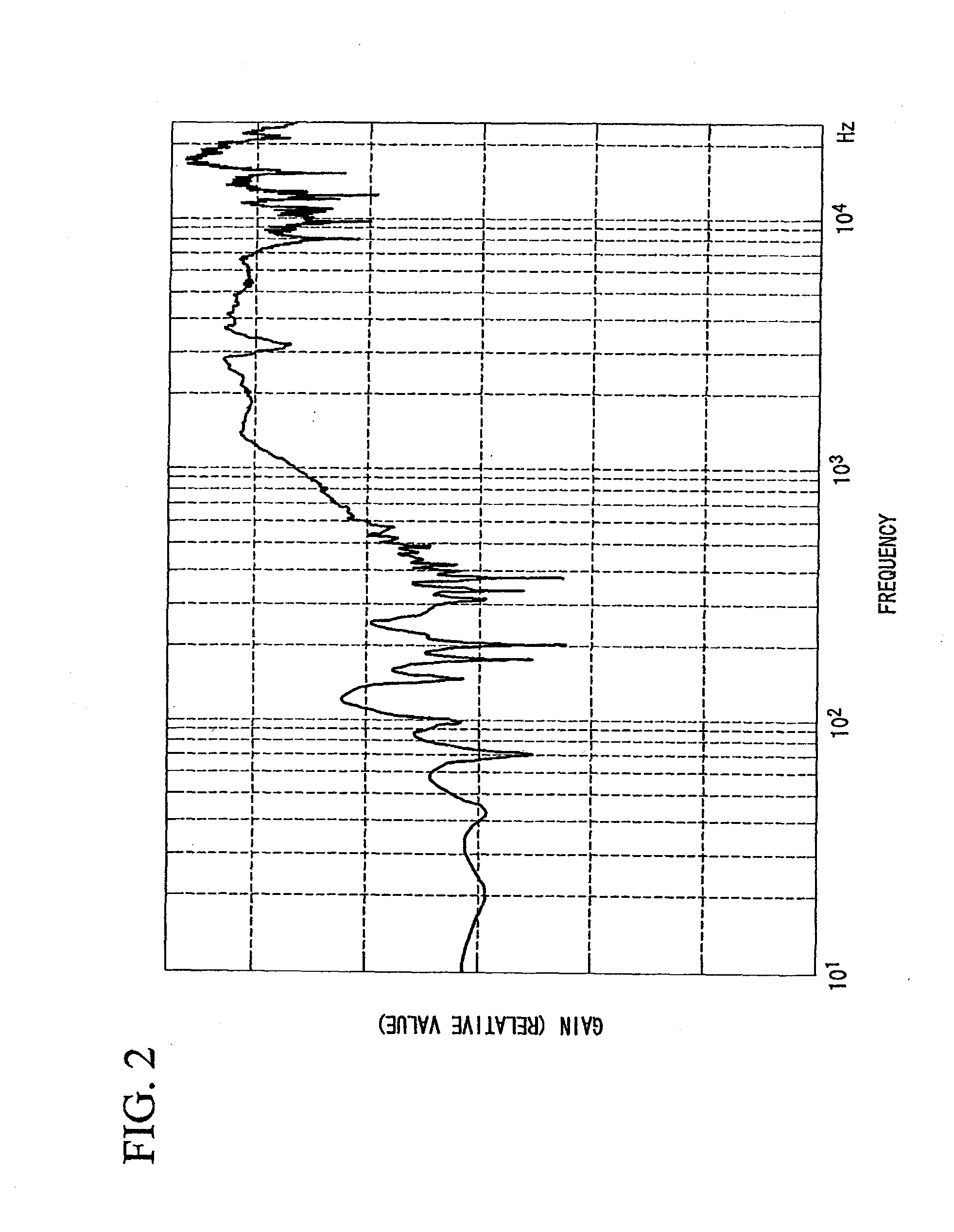
[0023]The echo canceler is designed to determine the double-talk event with respect to the prescribed frequency band, in which the signal level is attenuated due to the echo path lying between the speaker and the microphone and in which the echo is attenuated in level but the near-end talker's speech received by the microphone is not attenuated in level. This principle does not depend upon the special premise employed by a conventionally-known double-talk detection method; hence, it is possible to remarkably reduce error in double-talk detection. Since the double-talk detector of the echo canceler is simply designed to extract the above frequency band, it is possible to precisely detect a double-talk event with a simple constitution.

Problems solved by technology

Such a phenomenon causes discomfort for talkers, and a significantly large echo causes howling so as to cause auditory difficulty in communications.
Using any one of the algorithms, the filter coefficient of the adaptive filter 21 may be erroneously adjusted and updated in response to the speech v(t) of the near-end talker, thus making it very difficult to perform echo cancellation appropriately.
In actuality, such a premise is not normally established so that the first detection method suffers from erroneous detection of the speech v(t) of the near-end talker and degradation of communication quality due to erroneous detection.
The second method needs an additional scheme for detecting variations of an echo path, which increases calculations and memory capacities and which thus results in complexity of the constitution of an echo canceler.

Method used


Image

  • Acoustic echo canceler
  • Acoustic echo canceler
  • Acoustic echo canceler

Examples


Embodiment Construction

[0030]The present invention will be described in further detail by way of examples with reference to the accompanying drawings.

[0031]FIG. 1 is a block diagram showing the constitution of an echo canceler (or an acoustic echo canceling device) 10 according to a preferred embodiment of the present invention. The echo canceler 10 is installed in a portable telephone terminal (or a cellular phone) 1 so as to cancel an echo occurring in communication with a counterpart portable telephone terminal (not shown). The echo canceler 10 is essentially constituted of an adaptive filter 11, a double-talk detector 12, a subtracter 13, and a step-size controller 14. The double-talk detector 12 is constituted of a low-frequency extraction unit 121, a signal level calculation unit 122, a noise level calculation unit 123, and a comparator 124.

[0032]The portable telephone terminal 1 is equipped with a speaker 16 and a microphone 17, wherein the near-end talker uses the portable telephone terminal 1 to ...


PUM


Abstract

An echo canceler is constituted of an adaptive filter for generating an echo replica simulating an echo occurring in an echo path lying between a speaker and a microphone, a subtracter for subtracting the echo replica from the sound received by the microphone, a double-talk detector which extracts a prescribed frequency band, in which the signal level is attenuated due to the echo path, from the output signal of the subtracter and which determines a double-talk event with respect to the extracted frequency band, and a controller for controlling the adaptive filter to update the echo replica in the double-talk event.

Description

BACKGROUND OF THE INVENTION[0001]1. Field of the Invention[0002]The present invention relates to acoustic echo cancelers which cancel echoes occurring in communications.[0003]The present application claims priority on Japanese Patent Application No. 2008-89733, the content of which is incorporated herein by reference.[0004]2. Description of the Related Art[0005]Audio communication technologies allowing remote talkers (e.g. near-end talkers and far-end talkers located in remote places respectively) to perform conversations by use of communication devices having microphones and speakers have been widely used in telecommunication systems and television conference systems. In communications using communication devices, audio signals reproduced by speakers are partially input into microphones and mistakenly transmitted to counterpart communication devices, by which counterpart talkers may recognize their voices as echoes. Such a phenomenon causes discomfort for talkers, and a significant...

Claims


Application Information

Patent Timeline
Patent Type & Authority Applications(United States)
IPC IPC(8): H04M9/08H04B3/20
CPCH04M9/082H04B3/234
Inventor LIU, EN CAI
Owner YAMAHA CORP
Learn More