
Image reading apparatus, image reading method and image reading program

a reading apparatus and image technology, applied in the field of image reading, can solve the problem of adding noise to the read data outputted from a specific light receiving element array

Inactive Publication Date: 2009-10-01
KK TOSHIBA +1
View PDF3 Cites 6 Cited by
  • Summary
  • Abstract
  • Description
  • Claims
  • Application Information

AI Technical Summary

Benefits of technology

[0034]It is an object of an embodiment of the invention to provide an image reading apparatus in which cross-talk noise occurring between plural light receiving element arrays is reduced, an image reading method and an image reading program.
[0035]In order to solve the foregoing problem, according to an aspect of the invention, there are included plural reading units that read a read object, output a result of reading as read data including plural pixels, and respectively operate at different timings, a noise calculation unit that acquires first read data as a result of reading of a first read object as the read object by the plural reading units, acquires an operation state of the plural reading units during the reading of the first read object, and calculates, based on the operation state and the first read data obtained in the operation state, noise information based on the operation state, and a noise removal unit that acquires second read data as a result of reading of a second read object as the read object different from the first read object by the plural reading units, and removes noise from the second read data based on the noise information calculated by the noise calculation unit.

Problems solved by technology

However, in the case where the image reading apparatus includes plural light receiving element arrays as in the patent document 1, read data outputted from a specific light receiving element array is added with noise due to the influence of operation of another light receiving element array.

Method used


Image

  • Image reading apparatus, image reading method and image reading program
  • Image reading apparatus, image reading method and image reading program
  • Image reading apparatus, image reading method and image reading program

Examples


Embodiment Construction

[0056]Hereinafter, embodiments of the invention will be described with reference to the drawings.

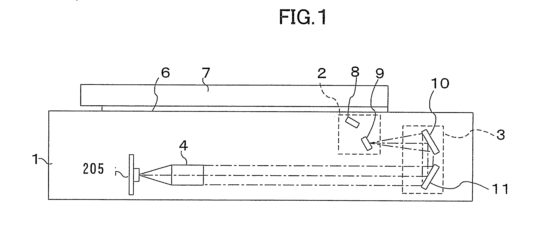
[0057]FIG. 1 is a block diagram showing an example of a structure of a mechanical system of an image reading apparatus of an embodiment. In this drawing, the same reference numeral as that of FIG. 14 denotes the same or equivalent part to that shown in FIG. 14 and its explanation will be omitted here. In this drawing, as compared with FIG. 14, a one-dimensional image sensor device 205 is provided instead of the one-dimensional image sensor device 5.

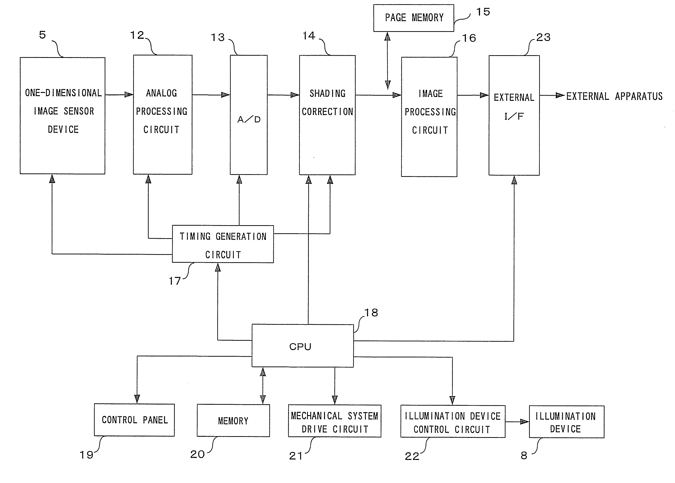
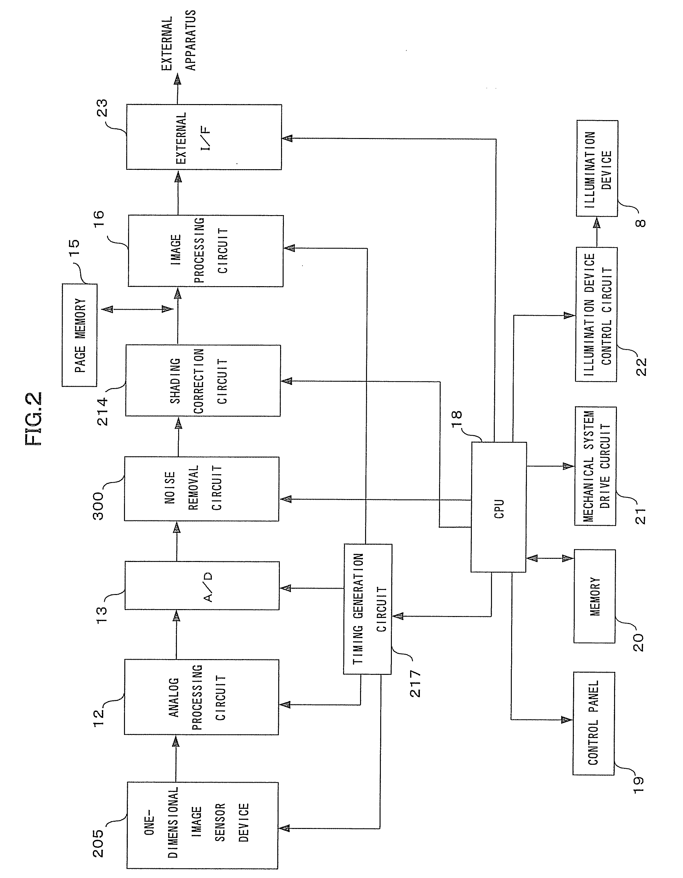
[0058]FIG. 2 is a block diagram showing an example of a structure of an electrical system of the image reading apparatus of the embodiment. In this drawing, the same reference numeral as that of FIG. 15 denotes the same or equivalent part to that shown in FIG. 15 and its explanation will be omitted here. In this drawing, as compared with FIG. 15, the one-dimensional image sensor device 205 is provided instead of the one-dimensional image senso...


PUM


Abstract

An image reading apparatus in which cross-talk noise occurring between plural reading units is reduced, an image reading method and an image reading program are provided. There are included plural reading units that respectively operate at different timings, a noise calculation unit that acquires first read data as a result of reading of a first read object as the read object by the plural reading units, acquires an operation state of the plural reading units during the reading of the first read object, and calculates, based on the operation state and the first read data obtained in the operation state, noise information based on the operation state, and a noise removal unit that acquires second read data as a result of reading of a second read object as the read object different from the first read object by the plural reading units, and removes noise from the second read data based on the noise information calculated by the noise calculation unit.

Description

BACKGROUND OF THE INVENTION[0001]1. Field of the Invention[0002]The present invention relates to an image reading apparatus in which a read result is corrected, an image reading method and an image reading program.[0003]2. Description of the Related Art[0004]First, a structure of a mechanical system of a related art image reading apparatus will be described.[0005]FIG. 14 is a block diagram showing an example of the structure of the mechanical system of the related art image reading apparatus. The mechanical system of the image reading apparatus includes a first carriage 2, a second carriage 3, a condensing lens 4, a one-dimensional image sensor device 5, an original document table glass 6, a platen cover 7, an illumination device 8, and mirrors 9, 10 and 11.[0006]An original document is placed on the original document table glass 6 so that the original document writing surface faces the original document table glass 6 side, and the platen cover 7 is closed so that the original docum...

Claims


Application Information

Patent Timeline
Patent Type & Authority Applications(United States)
IPC IPC(8): H04N1/38
CPCH04N1/409
Inventor KAWAI, KOJI
Owner KK TOSHIBA
Learn More