
Infeed station of a stack palletizing system and method for transferring stacks to a gripper with an infeed station of this type

a technology of stack palletizing system and infeed station, which is applied in the direction of stacking articles, conveying parts, de-stacking articles, etc., can solve the problems of space requirements and manufacturing costs, and achieve the effect of reliable centering of stacks, conveying and centered especially easily and reliably, and fast and simple changeover

Inactive Publication Date: 2009-09-24
MULLER MARTINI HLDG
View PDF11 Cites 8 Cited by
  • Summary
  • Abstract
  • Description
  • Claims
  • Application Information

AI Technical Summary

Benefits of technology

The invention is a new infeed station for transferring stacks of varying widths to a stack gripper. The station has two conveying means and two centering means that can be adjusted independently. This allows for both double infeed and single infeed of stacks, and ensures that the gripper can handle a wide range of stack formats. The infeed station can be easily moved and has rollers for reliable centering of the stacks. The technical effects of the invention are its versatility, flexibility, and ability to handle different stack formats.

Problems solved by technology

To process stacks that are relatively wide, the infeed station must be constructed correspondingly wide, but this is a disadvantage with respect to the amount of space that it requires and with respect to the manufacturing costs.

Method used


Image

  • Infeed station of a stack palletizing system and method for transferring stacks to a gripper with an infeed station of this type
  • Infeed station of a stack palletizing system and method for transferring stacks to a gripper with an infeed station of this type
  • Infeed station of a stack palletizing system and method for transferring stacks to a gripper with an infeed station of this type

Examples


Embodiment Construction

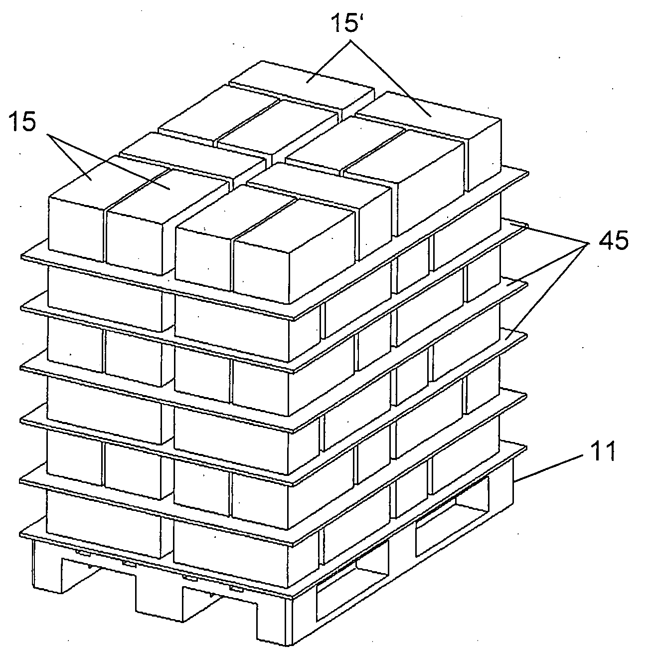
[0022]Stacks 15 and 15′ can be palletized on a pallet 11, as shown in FIG. 10, with the palletizing system 1 shown in FIG. 1. Cardboard separators 45 are arranged between the stacks 15 and 15′. The palletization itself is performed automatically and is controlled in such a way that the stacks 15 and 15′ are set down on the pallet 11 optimally and exactly. The cardboard separators 45 are also set down automatically. The stacks 15 and 15′ are any type of stacked products, preferably printed products, such as signatures, newspapers, books and the like. The stacks 15 and 15′ can be wrapped in sheets or bound in any other way, but this is not necessary. The stacks 15 and 15′ can also consist of individual printed products, for example, thick catalogues.

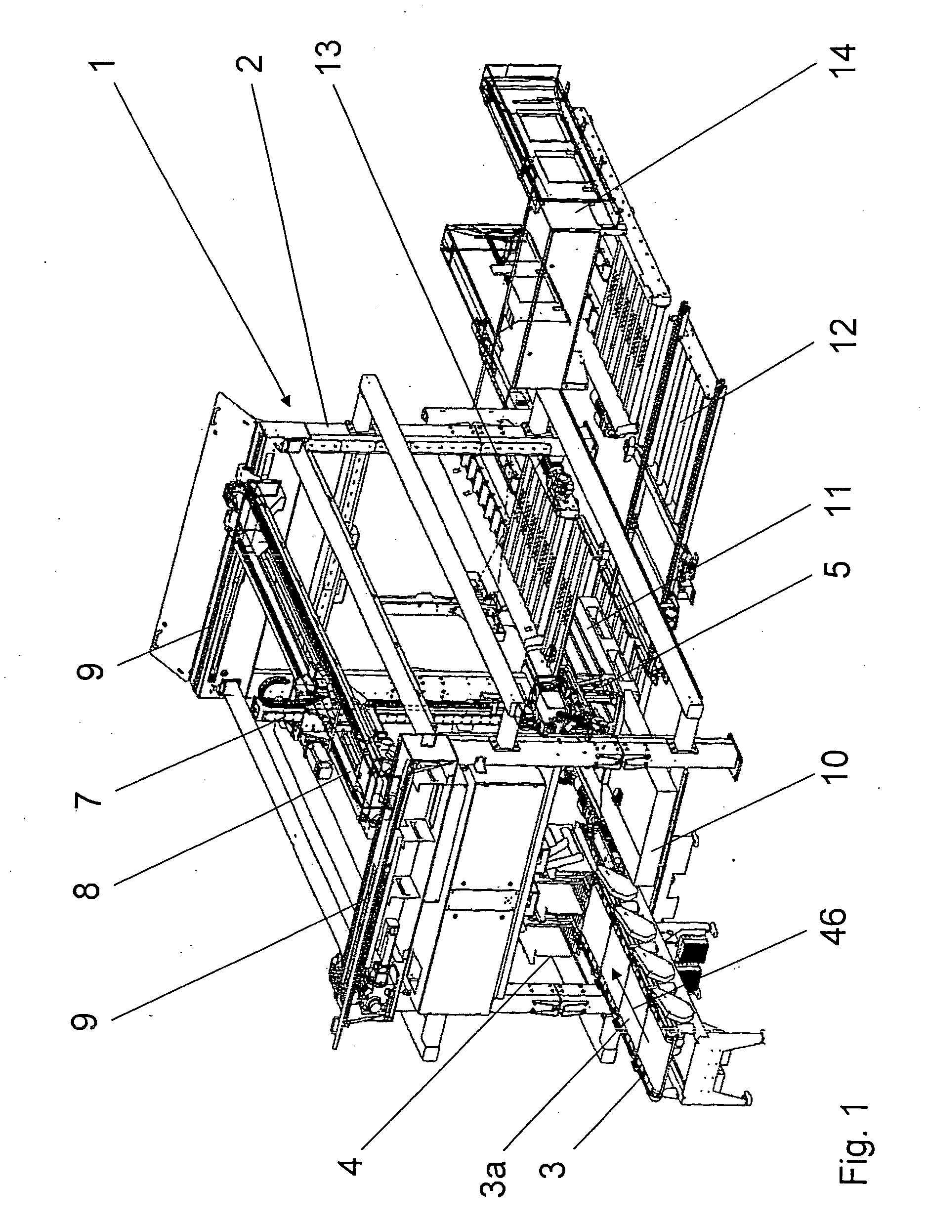
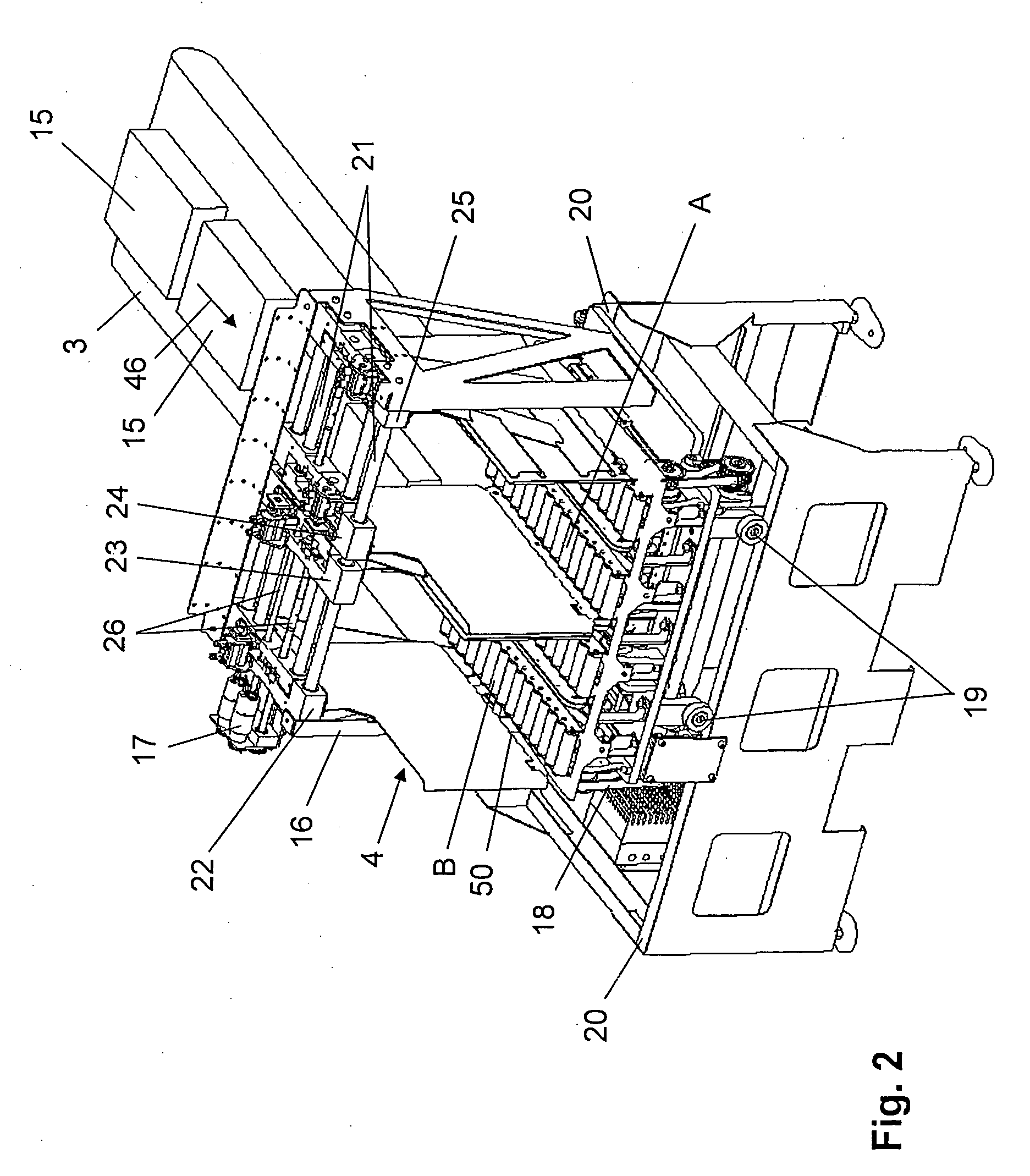
[0023]The palletizing system 1 consists of a machine frame 2, in front of which a stack feeder 3 is arranged, as shown in FIG. 1. The stack feeder 3 serves to feed the stacks 15 and 15′ to a stack infeed station 4, which is installed insid...


PUM


Abstract

An infeed station has a stack feeder and a first and second chamber, which can each receive stacks from the stack feeder. The stacks can be conveyed in the chambers and can be transferred to a stack gripper with the conveyors assigned to the first chamber and the second chamber. First centering units serve to center the stacks in the first chamber, and second centering units serve to center the stacks in the second chamber. Third conveyors are arranged between the first and second conveyors. The first and second centering units can be shifted relative to each other so that the third conveyors are positioned in the first or second chamber, and the chamber with the third conveyors is much wider than the other chamber. The infeed station can be changed between double infeed with parallel processing of two stacks and single infeed with processing of only one stack of relatively great width at a time.

Description

BACKGROUND OF THE INVENTION[0001]1. Field of the Invention[0002]The present invention relates to an infeed station of a stack palletizing system, with a stack feeder, a first and second chamber, which can each receive stacks from the stack feeder, first conveying means assigned to the first chamber and second conveying means assigned to the second chamber, with which stacks are conveyed in the chambers and can be transferred to a stack gripper, and first centering means for centering the stacks in the first chamber and second centering means for centering the stacks in the second chamber.[0003]2. Description of the Related Art[0004]A prior-art infeed station of this type is disclosed by EP 1 801 047 A. In the cited document, the station is referred to as a transfer unit and has a displacement unit, on which a carriage is mounted in such a way that it can be displaced horizontally and transversely to the direction of conveyance. Two placement means are provided. They are arranged sid...

Claims


Application Information

Patent Timeline
Patent Type & Authority Applications(United States)
IPC IPC(8): B65G1/00
CPCY10S414/12B65G61/00
Inventor RYF, MARCLIEBHEIT, STEFAN
Owner MULLER MARTINI HLDG
Learn More