
Accident sensor

a sensor and sensor technology, applied in the direction of screws, electrical apparatus casings/cabinets/drawers, instruments, etc., can solve the problems of sleeve with studs, only with great force, etc., and achieve the effect of cost saving

Active Publication Date: 2009-09-24
ROBERT BOSCH GMBH
View PDF13 Cites 9 Cited by
  • Summary
  • Abstract
  • Description
  • Claims
  • Application Information

AI Technical Summary

Benefits of technology

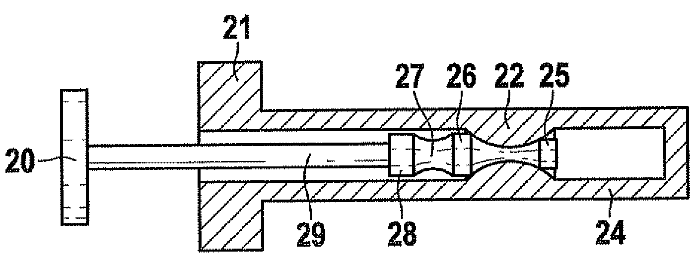
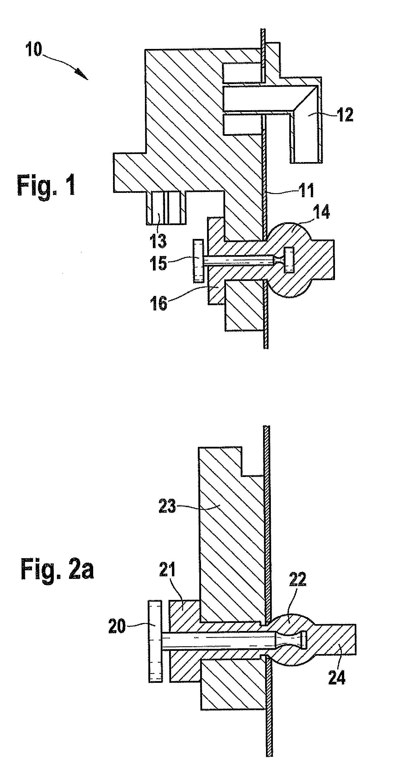
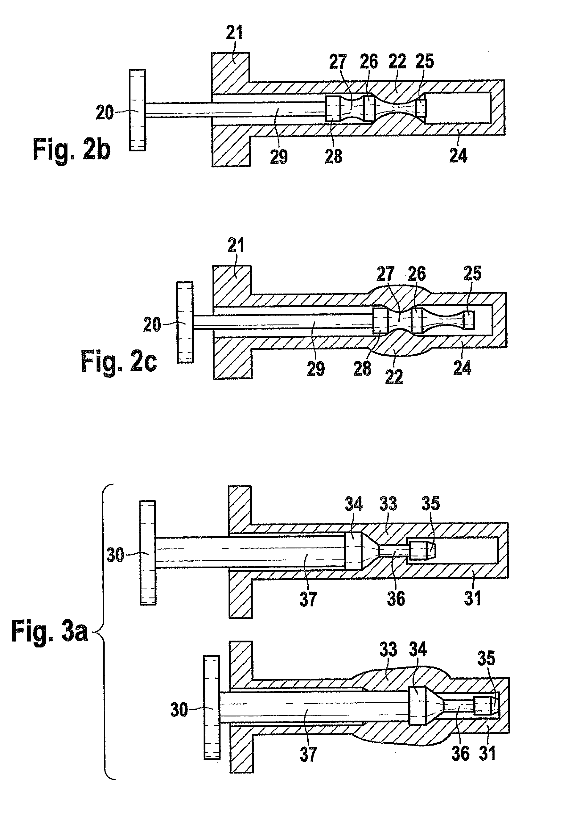
[0003]In contrast, the accident sensor according to the present invention having the features of the independent claim, has the advantage that the accident sensor hat as at least one bore hole, which has a stud in an elastic sleeve as the fastening arrangement. The stud with the sleeve is designed in such a way that the accident sensor with the stud in the sleeve is fixed in place in the wall by clamping. This allows an uncomplicated installation of the accident sensor on the wall in the vehicle, e.g., a door panel, no tools being required for the installation. In particular, this fastening method according to the present invention enables a one-handed installation since the other hand is not required for holding a tool. The stud with the sleeve simultaneously seals the hole in the wall so as to seal the dry space in which the accident sensor is located, from the wet space in an efficient manner. This simple method makes it possible to dispense with bushings in the sensor, in particular mechanical outer supports, as in the case of, for example, the screwing technology known from the related art. Due to the elastic shape of the sleeve, the fastening force and the mechanical hardness in the connection to the door panel, and thus also the resonance, can be influenced or specified, as well. In particular, high-frequency mechanical resonances are able to be damped in efficient manner in the process. On account of its design, the accident sensor according to the present invention provides considerable cost savings.

Problems solved by technology

Because of the clamping, it is impossible for the sleeve with stud, and thus the sensor itself, to simply fall out once it has been pushed through the bore hole in the wall, but instead can be pulled out only with great force.

Method used


Image

  • Accident sensor
  • Accident sensor
  • Accident sensor

Examples


Embodiment Construction

[0021]According to the exemplary embodiments and / or exemplary methods of the present invention, an accident sensor with a stud and a sleeve, which are guided through a bore hole in the accident sensor, is fixed in place on a wall in the vehicle in that the stud with the sleeve is threaded through a hole in the wall and supports the accident sensor by a clamping effect. Studs or screws may be used in addition so as to define the installation position more precisely. The more precise installation position can also be aptly defined by the use of the use of a plurality of studs with sleeves. In this context it is possible that the stud is already inside the sleeve before it is fixed in place in the wall or that it is inserted into the sleeve only for the mounting in the wall, after the sleeve has already been passed through the hole in the wall and the clamping effect is produced by an expansion of the sleeve behind the hole in the wall.

[0022]FIG. 1 schematically illustrates how an air ...


PUM


Abstract

An accident sensor having a fastening arrangement is provided, the fastening arrangement allowing an affixation of the accident sensor on a wall in a vehicle. The accident sensor has at least one bore hole, which has a stud in an elastic sleeve as a fastening arrangement. The stud with the sleeve is configured so that the accident sensor having the stud with the sleeve is affixed in the wall by a clamp.

Description

FIELD OF THE INVENTION[0001]The present invention relates to an accident sensor.BACKGROUND INFORMATION[0002]A sensor assembly in which the housing of an air-pressure sensor used for sensing side impacts is mounted on a wall in the vehicle with the aid of fastening arrangement, e.g., screws, is discussed in DE 199 23 985 A1. DE 191 06 311 A1 likewise teaches that an air-pressure sensor is installed in the wall of a partition wall between wet area and dry area in the door. The pressure channel projects into the wet area while the air-pressure sensor itself is situated in the dry area. A sealing cushion is provided, which seals the housing interior from the pressure sensor and also the housing from the partition wall.SUMMARY OF THE INVENTION[0003]In contrast, the accident sensor according to the present invention having the features of the independent claim, has the advantage that the accident sensor hat as at least one bore hole, which has a stud in an elastic sleeve as the fastening ...

Claims


Application Information

Patent Timeline
Patent Type & Authority Applications(United States)
IPC IPC(8): F16B13/06
CPCB60R21/01B60R2021/01006F16B13/126H05K5/0204F16B19/02F16B19/1081F16B19/002
Inventor BRANDT, TOBBYOHL, CHRISTIANADAM, BORISSCHUERER, MARTIN
Owner ROBERT BOSCH GMBH
Learn More