
Gravity Gradient Sensor

a gravity gradient and sensor technology, applied in the field of gravity gradient sensors, can solve the problems of partial isolation, complex and expensive isolation infrastructure, and easy exposure to extraneous vibrations, and achieve the effect of less susceptible to noise and less sensitive to nois

Inactive Publication Date: 2009-09-24
SYMPHONY ACOUSTICS
View PDF17 Cites 17 Cited by
  • Summary
  • Abstract
  • Description
  • Claims
  • Application Information

AI Technical Summary

Benefits of technology

[0014]In some embodiments, mechanical energy is conveyed between the sensors at the first location and the second location. As a result, such embodiments are less susceptible to noise due to shock, vibration, and external acceleration.
[0015]In some embodiments, thermal energy is conveyed between the sensors at the first location and the second location. As a result, such embodiments are less sensitive to noise due to thermal gradients between the two locations.

Problems solved by technology

The high-sensitivity of a gravimeter makes it susceptible to extraneous vibrations.
Unfortunately, such isolation requires complex and expensive infrastructure and affords only partial isolation.
This requires, however, a highly developed model of the noise sources and also adds to the cost and complexity of the gravimeter system.
Although time averaging offers improvement in gravimeter sensitivity, it precludes the use of such systems in many applications.

Method used


Image

  • Gravity Gradient Sensor
  • Gravity Gradient Sensor
  • Gravity Gradient Sensor

Examples


Embodiment Construction

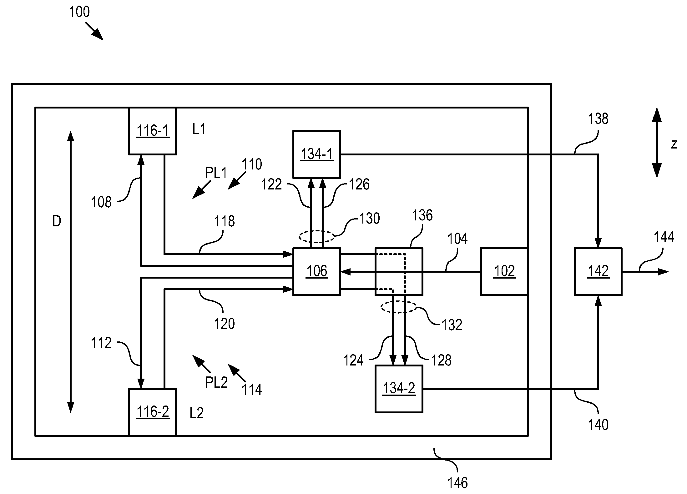
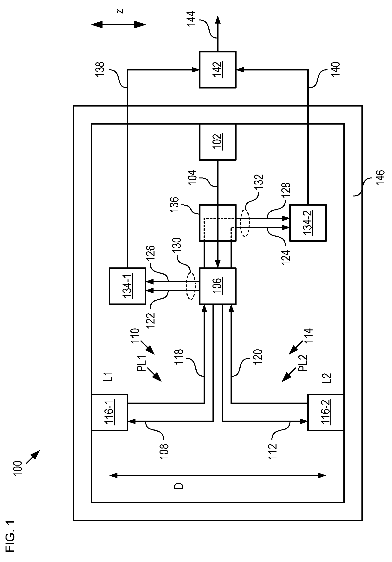
[0027]FIG. 1 depicts a schematic diagram of details of a differential gravimeter in accordance with an illustrative embodiment of the present invention. Gravimeter 100 comprises source 102, beam splitter 106, sensors 116-1 and 116-2, photodetectors 134 and 138, processor 142, and frame 146.

[0028]Gravimeter 100 provides an output signal based on a difference in a first gravitational field at location L1 that is aligned with the z-direction and a second gravitational field at location L2 that is aligned with the z-direction. For the purposes of this specification, including the appended claims, the axes and / or directions are “aligned” if they are collinear, or if they are non-collinear but are substantially parallel.

[0029]FIG. 2 depicts a method for sensing a gravity gradient between two locations in accordance with the illustrative embodiment of the present invention. Method 200 is described with continuing reference to FIG. 1.

[0030]FIG. 3 depicts a schematic drawing depicting detail...


PUM


Abstract

A gravimeter for detecting a gravity difference between two points is disclosed. The gravimeter comprises an interferometric arrangement wherein the length of a reference arm is dependent upon the gravity local to a first accelerometer and the length of a sample arm is dependent upon the gravity local to a second accelerometer. A pair of photodetectors that operate in complimentary fashion provide electrical signals based on a first signal conveyed by the reference arm and a second signal conveyed by the sample arm. A change in the differential gravity between the two points induces equal and opposite changes to the magnitudes of the two electrical signals.

Description

CROSS REFERENCE TO RELATED APPLICATIONS[0001]This case claims priority to: U.S. Provisional Patent Application Ser. No. 61 / 037,661, filed Mar. 18, 2008 (Attorney Docket: 123-090US), which is incorporated by reference.[0002]If there are any contradictions or inconsistencies in language between this application and one or more of the cases that have been incorporated by reference that might affect the interpretation of the claims in this case, the claims in this case should be interpreted to be consistent with the language in this case.FIELD OF THE INVENTION[0003]The present invention relates to gravimeters in general, and, more particularly, to gradient gravimeters.BACKGROUND OF THE INVENTION[0004]Gravimetric sensing is a powerful tool for used in such applications as geological surveying, oil field exploration, earthquake detection, homeland defense, and shipping container shock detection. A gravimeter is an instrument used measuring a local gravitational field. A gravimeter is a hi...

Claims


Application Information

Patent Timeline
Patent Type & Authority Applications(United States)
IPC IPC(8): G01V7/00G01B9/02
CPCG01V7/00
Inventor CARR, DUSTIN WADE
Owner SYMPHONY ACOUSTICS
Learn More