
Image reading device and image forming device

a reading device and a technology of forming device, applied in the direction of instruments, electrographic process devices, optics, etc., can solve the problems of inefficient use of large portion of the internal space of the carriage, and inability to reduce the material cost of the whole mirror group, including the plurality of mirrors, so as to increase the load applied to the motor

Active Publication Date: 2009-09-17
KYOCERA DOCUMENT SOLUTIONS INC
View PDF7 Cites 0 Cited by
  • Summary
  • Abstract
  • Description
  • Claims
  • Application Information

AI Technical Summary

Benefits of technology

[0013]Moreover, in a case where the plurality of mirrors are large in mass, that inertia force generated by locomotion of the carriage becomes greater, thereby increasing a load applied to a motor and the like that moves the carriage.

Problems solved by technology

In addition, in the image reading device of Patent Document 1, there was a problem in that the plurality of mirrors occupies a large portion of an internal space of the carriage.
In other words, there was a problem in that the internal space of the carriage is not used efficiently.
Furthermore, since the plurality of mirrors is formed to have a width corresponding to the widest luminous flux, a material cost for a whole mirror group, including the plurality of mirrors, cannot be reduced.

Method used


Image

  • Image reading device and image forming device
  • Image reading device and image forming device
  • Image reading device and image forming device

Examples


Embodiment Construction

[0037]A preferred embodiment of the present invention is described hereinafter with reference to the drawings.

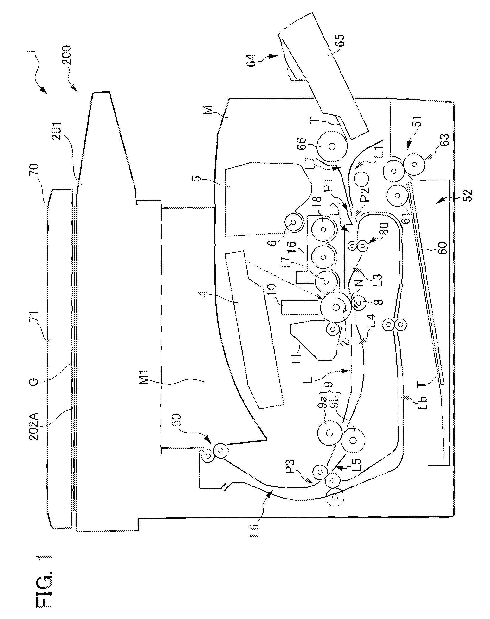
[0038]An overall structure of a copy machine 1 as an image forming device according to the present embodiment is described referring to FIG. 1. FIG. 1 is a left lateral view showing disposition of components of the copy machine 1. In the present embodiment, a side on which a manual feeding tray 65 (described later) is disposed (a right side in FIG. 1) is a front side of the copy machine 1.

[0039]The copy machine 1 as the image forming device includes: an image reading device 200 disposed on an upper side thereof; and a device main body M disposed on a lower side thereof that forms a toner image on a paper T on the basis of image information from the image reading device 200.

[0040]The image reading device 200 includes an original feeder portion 70 for feeding a predetermined original G, and a reader portion 201 for reading an image on the original G. The original feeder portio...


PUM


Abstract

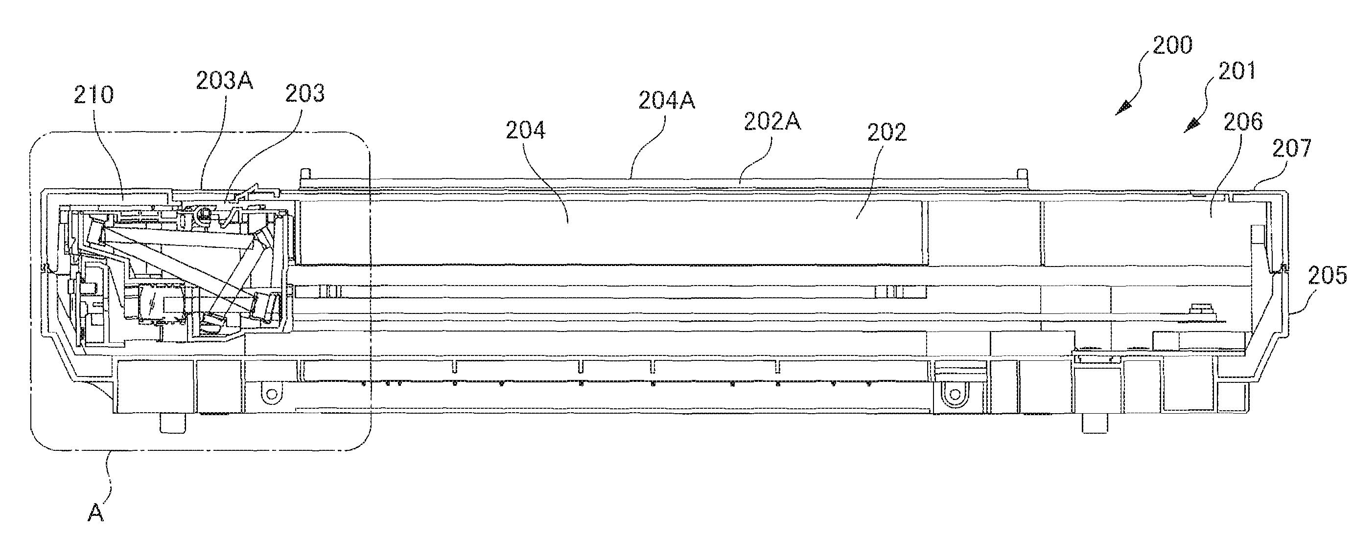
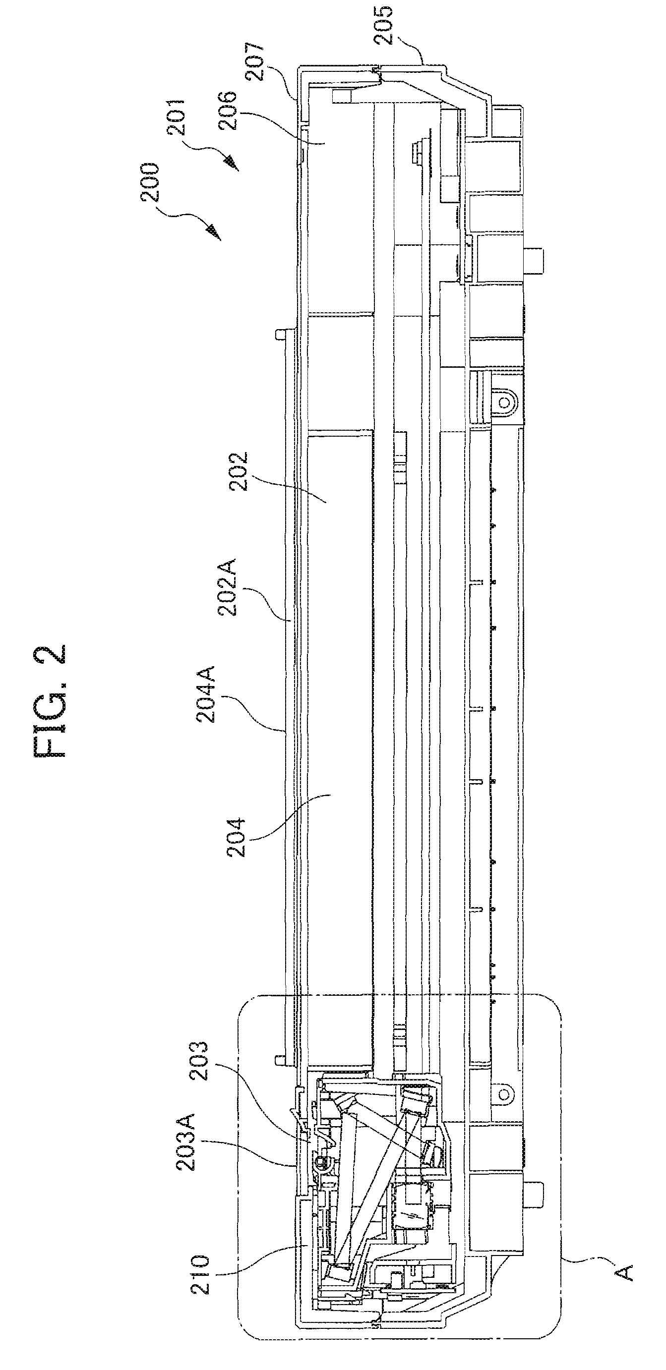
A copy machine is provided which includes: a fluorescent lamp; a mirror group having a plurality of mirrors that forms a light path by reflecting luminous flux from an original once on each of the plurality of mirrors, and is configured so that an imaging-side mirror, which is disposed most to an imaging side on the light path, has a shortest length in a main scanning direction; an imaging lens that forms an image from luminous flux reflected by the mirror group; a reading portion that reads an image on the original based on image formation by the imaging lens, disposed in an imaging position of the imaging lens; and a casing body that houses the fluorescent lamp, the mirror group, the imaging lens, and the reading portion, to be movable in a sub-scanning direction that is orthogonal to the main scanning direction.

Description

[0001]This application is based on and claims the benefit of priority from Japanese Patent Application No. 2008-061021, filed on 11 Mar. 2008, the content of which is incorporated herein by reference.BACKGROUND OF THE INVENTION[0002]1. Field of the Invention[0003]The present invention relates to an image reading device and an image forming device including an image reading device.[0004]2. Related Art[0005]Conventionally, an image reading device for scanning an image on an original has been known, including a carriage for housing in an integrated manner: a light source for irradiating light on the original; an imaging lens for forming an image from luminous flux from the original; and a CCD (charge-coupled device), in which the carriage scans the image on the original while moving in a sub-scanning direction that is orthogonal to a main scanning direction.[0006]Here, an optical path of a predetermined distance is required in the image reading device, for focusing the overall luminous...

Claims


Application Information

Patent Timeline
Patent Type & Authority Applications(United States)
IPC IPC(8): G03G15/00
CPCG03G2215/00185H04N1/03H04N1/193H04N1/0305H04N1/1017H04N1/0303
Inventor HOZONO, TOMOHIDE
Owner KYOCERA DOCUMENT SOLUTIONS INC
Learn More