Splicer with Splicing Cassette Carrier

a cassette carrier and splicer technology, applied in the direction of instruments, optics, optical light guides, etc., can solve the problems of severe shaking, inability of the splicer to carry out a sudden rotary movement, etc., to reduce current consumption, prolong the operational readiness of the splicer, and reduce power consumption

Inactive Publication Date: 2009-09-17
CCS TECH INC
View PDF4 Cites 2 Cited by
  • Summary
  • Abstract
  • Description
  • Claims
  • Application Information

AI Technical Summary

Benefits of technology

[0025]By way of example, the first operating mode corresponds to a standby mode. The control unit operates the splicer in the standby mode, in which the power consumption is reduced, when the splicing cassette carrier is closed. This makes it possible to lengthen the operational readiness of the splicer.
[0026]However, it is also possible to reduce the current consumption when the splicing cassette carrier is open. For this purpose, the display apparatus has background lighting, the light intensity of which is variable. By way of example, a brightness sensor is provided in the control apparatus and detects the environmental brightness of the splicer when the splicing cassette carrier is open. The control unit operates the display apparatus such that the light intensity of the background lighting is set as a function of the environmental brightness detected by the brightness sensor. The power consumption of the display apparatus when the splicing cassette carrier is open can therefore be reduced in a bright environment.

Problems solved by technology

In this case, when the splicer is lifted with the aid of the handle, that is to say with the aid of the splicing cassette carrier, it is not possible for the splicer to carry out a sudden rotary movement relative to the splicing cassette carrier, which is held fixed.
The splicer can therefore be lifted and placed down safely without this resulting in severe shaking.

Method used


Image

  • Splicer with Splicing Cassette Carrier
  • Splicer with Splicing Cassette Carrier
  • Splicer with Splicing Cassette Carrier

Examples


Embodiment Construction

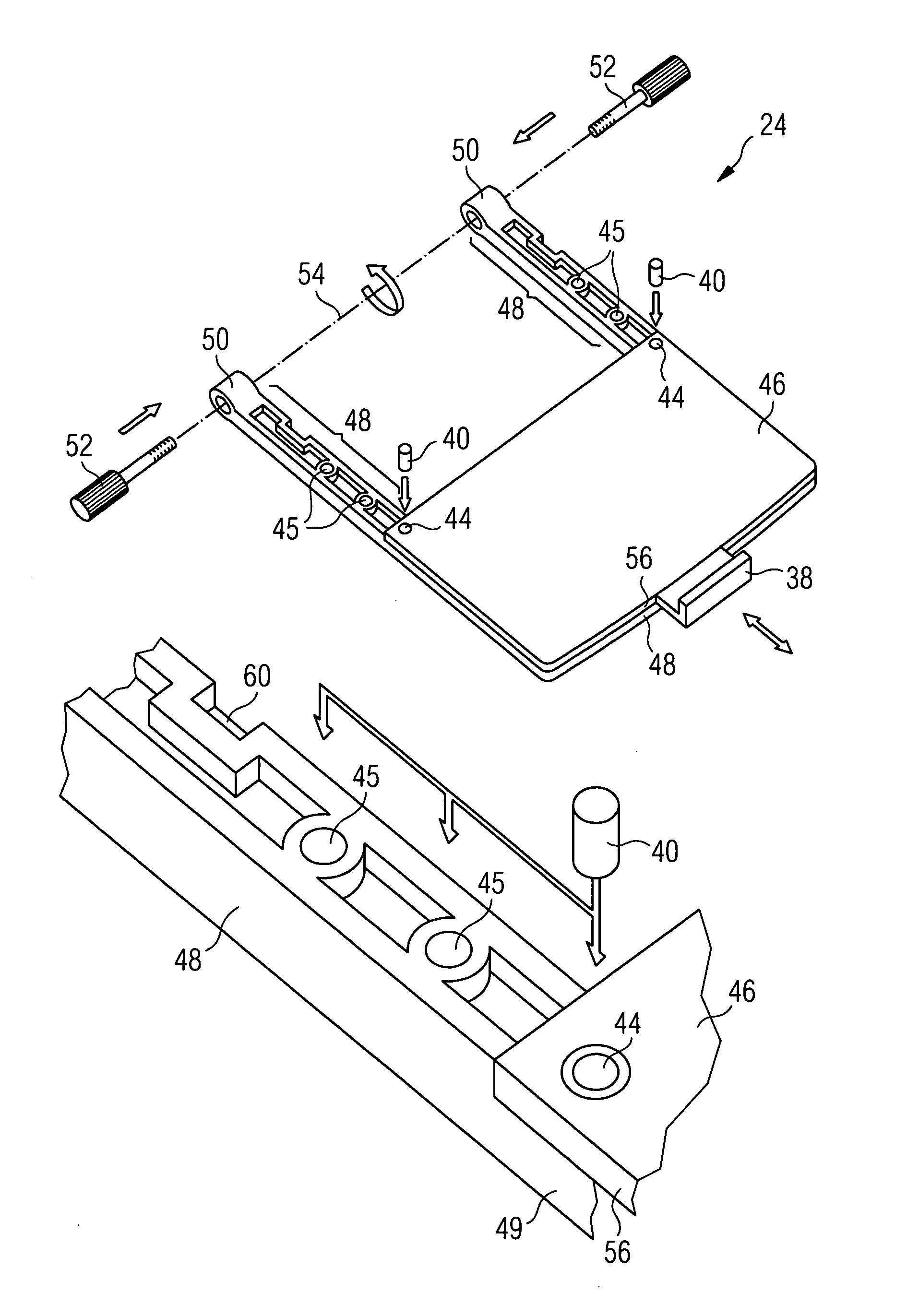
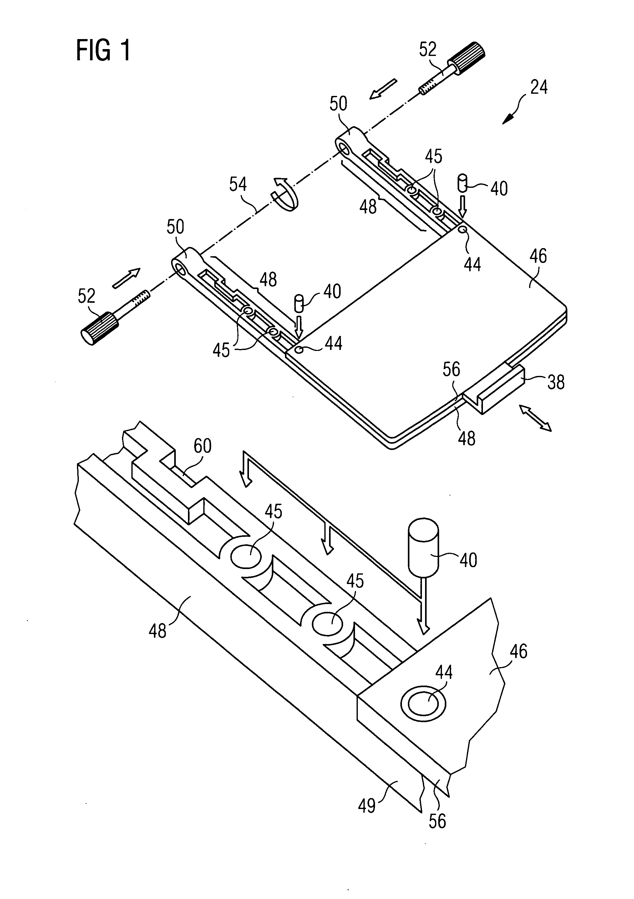
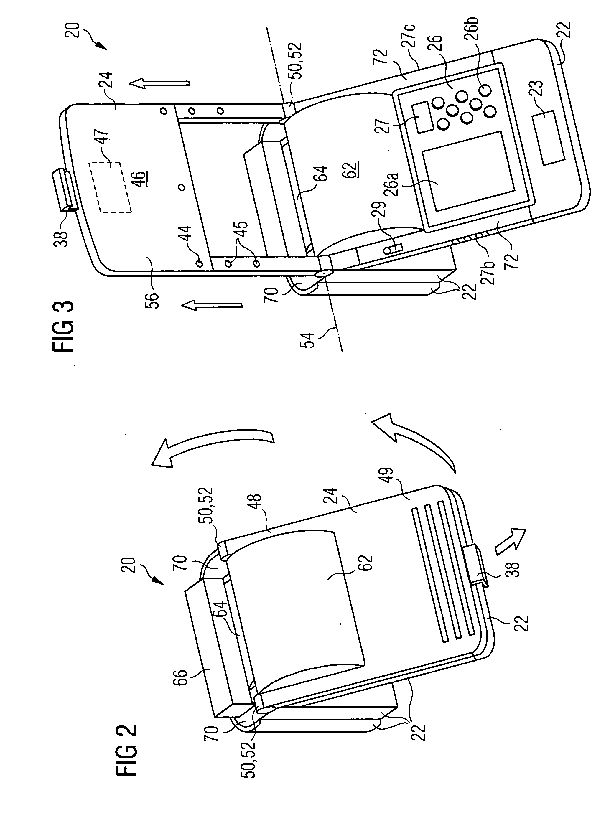
[0035]FIG. 1 shows a perspective illustration of a splicing cassette carrier 24 according to one exemplary embodiment of the invention. The splicing cassette carrier 24 can be seen in its entirety in the upper half of the figure, while the lower half of FIG. 1 shows an enlarged detail of the carrier arm 48.

[0036]The splicing cassette carrier 24 comprises a plate 56 which has a flat surface 46 and may be made, for example, from metal or from plastic. The plate 56 is used to accommodate a splicing cassette 36 (see FIG. 5). The splicing cassette carrier 24 also has two carrier arms 48, which lengthen the flat surface 46 of the plate 56 beyond its edge. The carrier arms 48 have two functions. On the one hand, they make the plate 56 robust by also continuing as elements 49 underneath the plate 56 thus ensuring that the metal plate is in a stable position at a given rotation angle and preventing torsion, while on the other hand they connect the metal plate to bushes 50 which are part of a...


PUM


Abstract

A splicer comprises a chassis with an opening in which a splicing unit for splicing of optical waveguides is arranged. The splicer can be controlled via a control and display apparatus. A splicing cassette carrier is arranged rotatably on the chassis. The splicing cassette carrier is designed such that it can be used both for fixing a splicing cassette or else as a carrying handle for the splicer. Furthermore, the splicer has a control unit via which the splicer is switched to an active operating mode or to a standby mode, as a function of the rotation position of the splicing cassette carrier. When the splicing cassette carrier is open, the light intensity of background lighting for the display apparatus and the light intensity of a lighting device can be controlled so they are variable. The reduced power consumption associated with this allows the operational readiness of the splicer to be lengthened.

Description

FIELD OF THE INVENTION[0001]The invention relates to a splicer with a splicing cassette carrier for holding a splicing cassette while optical waveguides or optical fibers are being spliced in the splicer. The invention also relates to mobile or portable lightweight splicers, which can be transported and used by one operator, in order to splice optical fibers inside or outside closed buildings.TECHNICAL BACKGROUND[0002]Splicers are used in a wide technical field, although they are particularly suitable for splicing optical waveguides and optical fibers. Mobile splicers are particularly suitable for use in the field, and are used when, for example, optical fibers are spliced on a mast or for an underground cable. A mobile splicer such as this typically comprises a splicing unit, a control and display unit, a shrinking unit and a chassis which accommodates these units. The splicer generally has an associated splicing cassette carrier, which is used to accommodate the splicing cassettes...

Claims


Application Information

Patent Timeline
Patent Type & Authority Applications(United States)
IPC IPC(8): G02B6/255G02B6/00
CPCG02B6/2551
Inventor DETEMPLE, THOMASKRONAWITTER, HEINZFORLENZA, MARCOHEIDLER, CHRISTIANKLAHR, MARTINKOSSAT, RAINER
Owner CCS TECH INC
Why Eureka
Try Eureka