
Vehicle Air Conditioner

a vehicle air conditioner and air-mixing technology, applied in the direction of machine operation, light and heating apparatus, transportation and packaging, etc., can solve the problems of reducing heating ability, and reducing heat exchange efficiency, so as to reduce noise, improve performance, and reduce pressure loss

Inactive Publication Date: 2009-09-17
MITSUBISHI HEAVY IND LTD
View PDF10 Cites 6 Cited by
  • Summary
  • Abstract
  • Description
  • Claims
  • Application Information

AI Technical Summary

Benefits of technology

[0009]However, according to Patent Document 1, the air flow stagnates at the curved portion protruding outward from the channel, and according to Patent Document 2, the air flow is separated at the straight vertical sidewall. The stagnation and separation causes the heating ability to decrease due to a decrease in the air volume. In particular, in the area below the heater core, the air volume and the air velocity are reduced, causing the air-velocity distribution of the heater core to be degraded. As a result, the heat-exchange efficiency is reduced, causing a problem of reduced heating ability. Moreover, vortexes generated by the stagnation and separation cause noise to increase. In particular, in recent vehicles, the air conditioner noise is one noticeable noise source in the vehicle interior since the engine noise and driving noise have been reduced, and thus, there is an urgent need to reduce such noise.
[0010]The present invention has been conceived in light of the problems described above. Accordingly, it is an object of the present invention to provide a vehicle air conditioner that is capable of improving the heat-exchange efficiency of the heater core by improving the air inlet channel of the heater core and suppressing stagnation and separation of an air flow so as to increase the heating ability and that is capable of reducing noise.
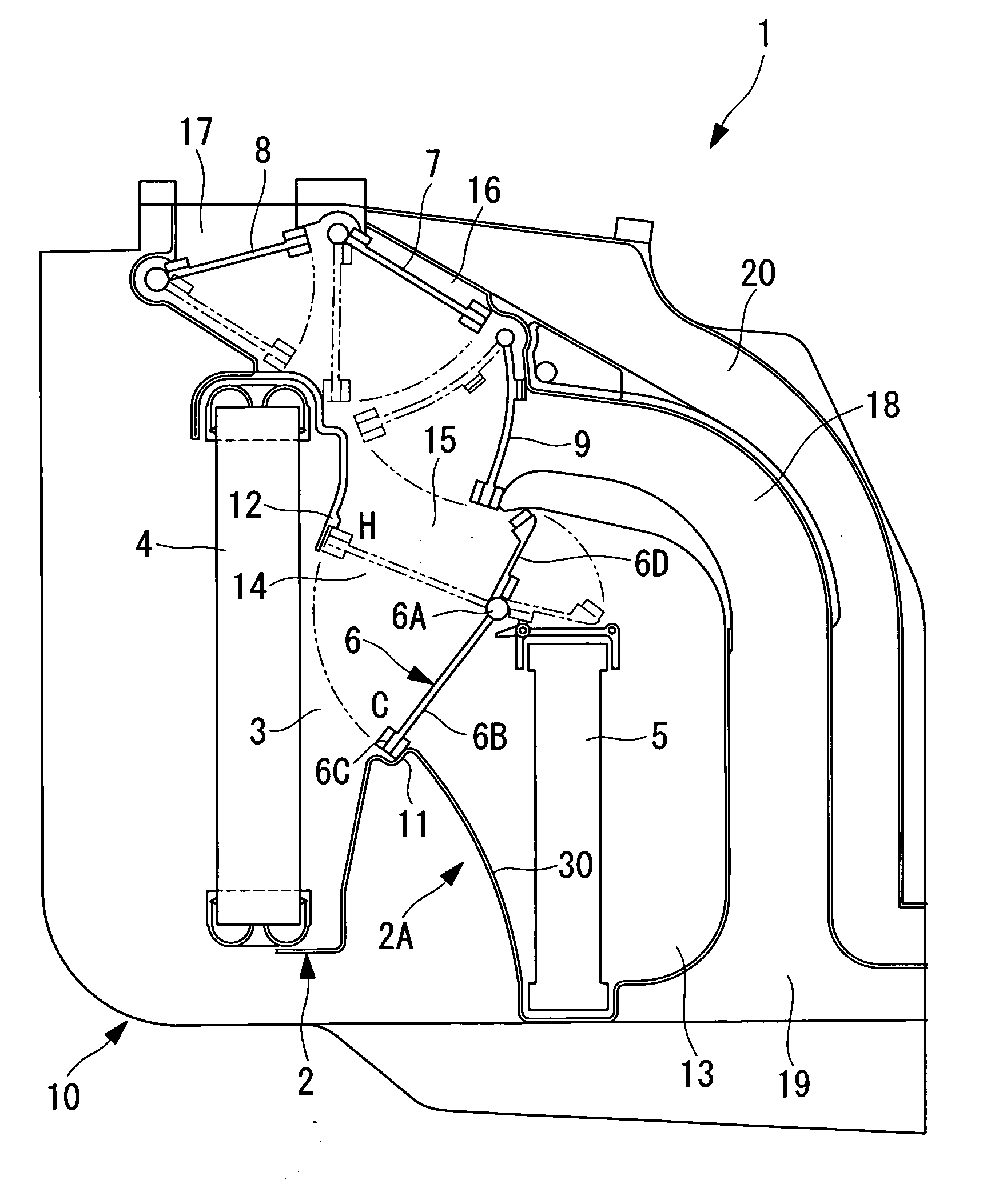
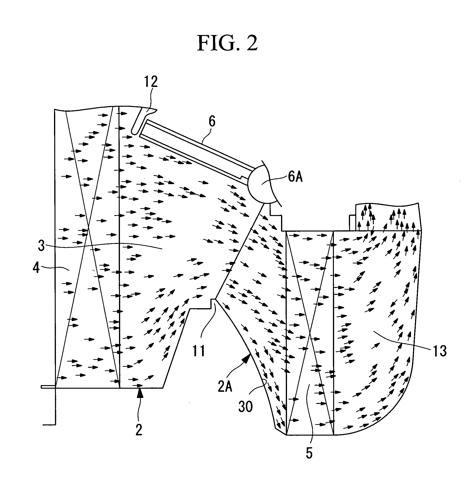
[0013]According to the present invention, the inlet-channel sidewall of the heater core is an inclined surface and this inclined surface is formed as a curved surface protruding toward the inlet channel of the heater core. Therefore, in the air flow guided to the heater core through the evaporator, the air flow along the inclined surface of the inlet channel of the heater core is attached to the curved surface of the inclined surface by means of the Coanda effect and is guided to the edge of the heater core without stagnation or separation, and heat exchange is carried out at the heater core. Therefore, an air flow can be guided substantially evenly on the entire surface of the heater core, and the velocity distribution of the air flow passing through the heater core can be made even. Therefore, the heat-exchange efficiency of the heater core can be improved, and the heating ability can be increased. Moreover, since stagnation and separation of the air flow at the inlet channel of the heater core can be suppressed, noise caused by vortexes due to stagnation or separation can be reduced, and the noise of the air conditioner can be reduced.
[0015]According to the present invention, the evaporator and the heater core are disposed parallel to each other, and the curved inclined surface is inclined from the sealing portion to the edge of the heater core with respect to a direction orthogonal to the evaporator. Therefore, the inclined surface from the sealing portion to the edge of the heater core can be a relatively gradually inclined surface. In this way, the air flow from the sealing portion to the heater core along the inclined surface can be attached to the curved inclined surface by means of the Coanda effect and can be smoothly guided to the edge of the heater core. Accordingly, stagnation and separation of the air flow at the inlet channel of the heater core and pressure loss can be suppressed, and noise caused by such problems can be reduced. Moreover, since an air flow can be guided substantially evenly over the entire surface of the heater core and the velocity distribution of the air flow passing through the heater core can be made even, the heat-exchange efficiency of the heater core can be improved, and the heating ability can be increased.
[0017]According to the present invention, since the evaporator and the heater core are disposed substantially vertically and parallel to each other, the air flow that horizontally passes through the evaporator flows diagonally downward toward the heater core and then flows downstream through the heater core horizontally. In this air flow, the air that flows from the sealing portion to the heater core along the inclined surface is attached to the relatively gradually inclined curved surface, is smoothly guided to the edge of the heater core, and flows through the heater core substantially horizontally. In this way, the entire air flow smoothly flows to reduce pressure loss due to the resistance of the channel, performance can be improved, and noise can be reduced.
[0018]According to the present invention, the air flow along the inclined surface of the inlet channel to the heater core is guided to the edge of the heater core while being attached to the curved inclined surface by means of the Coanda effect, the air flows into the heater core without stagnation or separation. Therefore, the air flow can be guided over the entire surface of the heater core in a substantially even manner, and the velocity distribution of the air flow passing through the heater core can be made even. Therefore, the heat-exchange efficiency of the heater core can be improved, and the heating ability can be increased. Furthermore, since stagnation and separation of an air flow at the inlet channel of the heater core can be suppressed, noise caused by vortexes due to stagnation or separation can be reduced, and noise of the air conditioner can be reduced.

Problems solved by technology

The stagnation and separation causes the heating ability to decrease due to a decrease in the air volume.
As a result, the heat-exchange efficiency is reduced, causing a problem of reduced heating ability.
Moreover, vortexes generated by the stagnation and separation cause noise to increase.
In particular, in recent vehicles, the air conditioner noise is one noticeable noise source in the vehicle interior since the engine noise and driving noise have been reduced, and thus, there is an urgent need to reduce such noise.

Method used


Image

  • Vehicle Air Conditioner
  • Vehicle Air Conditioner
  • Vehicle Air Conditioner

Examples


Embodiment Construction

[0034]An embodiment of the present invention will be described below with reference to the drawings.

[0035]An embodiment of the present invention will be described below with reference to FIGS. 1 and 2.

[0036]FIG. 1 is a cross-sectional view of the structure of a vehicle air conditioner according to an embodiment of the present invention. A vehicle air conditioner 1 includes a resin casing 2 that is connected to a blower unit which is not shown in the drawings. An air channel 3 that guides an air flow from the blower unit is provided inside the casing 2. The casing 2 is provided as a plurality of separate pieces. Air conditioner components, such as an evaporator 4, a heater core 5, an air-mixing damper 6, and a plurality of blowing-mode switching dampers 7, 8, and 9, are provided inside the casing 2 and are assembled as a single unit to form an HVAC unit 10.

[0037]At the downstream side of the evaporator 4, the air channel 3 is throttled by upper and lower sealing portions 11 and 12 co...


PUM


Abstract

An object is to provide a vehicle air conditioner that has increased heating ability and reduced noise by improving the heat-exchange efficiency of a heater core by improving an air inlet channel of the heater core and that suppresses stagnation and separation of an air flow at the air inlet channel. Provided is an air-mixing damper type vehicle air conditioner (1) including an air-mixing damper (6), wherein a heater-core inlet channel sidewall (2A) of a casing (2) from a sealing portion (11) of the casing (2) to an edge of a heater core (5) is an inclined surface (30), the sealing portion (11) being contacted by a tip portion (6C) of the air-mixing damper (6) when the inlet of a heating-side air channel (13) is completely closed, and wherein the inclined surface (30) is formed as a curved surface protruding toward the inlet channel of the heater core (5).

Description

TECHNICAL FIELD[0001]The present invention relates to an air-mixing type vehicle air conditioner including an air-mixing damper interposed between an evaporator and a heater core.BACKGROUND ART[0002]A large proportion of vehicle air conditioners employs an air mixing method for temperature control. An air-mixing type vehicle air conditioner includes a heater core disposed downstream of an evaporator provided in an air channel of a casing and a bypass channel for bypassing the heater core. The air-mixing type air conditioner regulates temperature by using an air-mixing damper to regulate the flow rate of an air flow to be reheated by the heater core in the air flow cooled at the evaporator and by mixing the air flow that is reheated at the heater core and the air flow that bypasses the heater core at a downstream air-mixing area.[0003]In many cases, the air-mixing damper is supported between the evaporator and the heater core such that a rotary shaft thereof is rotatable near one end...

Claims


Application Information

Patent Timeline
IPC IPC(8): B60H1/00
CPCB60H1/00028B60H2001/006B60H2001/00092B60H1/0005
Inventor CHIKAGAWA, NORIYUKISAKAGUCHI, ASUKA
Owner MITSUBISHI HEAVY IND LTD
Learn More