
Clipping device

a clipping device and endoscopic technology, applied in wound clamps, medical science, surgery, etc., can solve the problems of blades not spreading properly, blades not having sufficient elasticity, and inability to obtain a strong clamping force to maintain the grasp etc., to achieve strong clamping force of the clip, facilitate manipulation, and facilitate clipping and clip loading

Inactive Publication Date: 2009-09-10
FUJIFILM CORP
View PDF2 Cites 131 Cited by
  • Summary
  • Abstract
  • Description
  • Claims
  • Application Information

AI Technical Summary

Benefits of technology

[0007]It is an object of the present invention to solve the above-mentioned problems in the related art and to provide a clipping device including a clamping ring realizing both the function of preventing the clip from retreating into the sheath at the time of clipping manipulation and a strong clamping force of the clip, and making it possible to perform clipping and clip loading through easy manipulation.
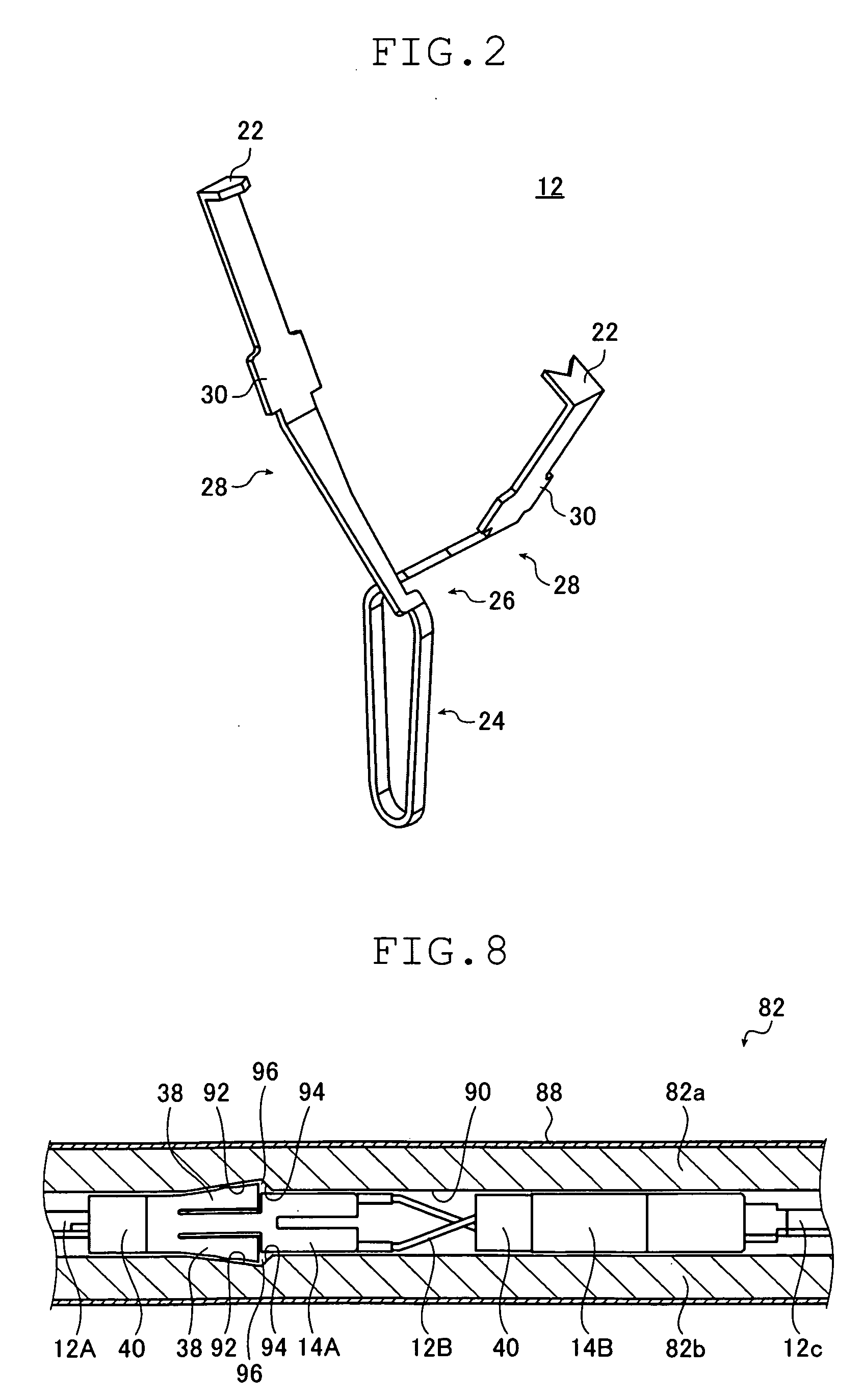
[0013]a resin retaining portion which has, at the same position in a clip pulling direction and at positions circumferentially spaced apart from each other, two or more skirt portions which, when being situated inside the sheath, are closed inwardly by being pressed by an inner wall of the sheath and which, when being situated outside of a forward end of the sheath, are opened in a width larger than an inner diameter of the sheath to prevent retreat into the sheath, and
[0020]a resin retaining portion which has, at the same position in a clip pulling direction and at positions circumferentially spaced apart from each other, two or more skirt portions which, when being situated inside the sheath, are closed inwardly by being pressed by an inner wall of the sheath and which, when being situated outside of a forward end of the sheath, are opened in a width larger than an inner diameter of the sheath to prevent retreat into the sheath, and

Problems solved by technology

However, when the clip clamping ring is made of a resin, it may be impossible to obtain a clamping force strong enough to maintain the grasping force of the clip depending upon the size and hardness of the living tissues to be grasped.
When the clip clamping ring is made of metal, it is impossible to endow the blade portions with sufficient elasticity, and hence there is a fear of the blades not spreading properly when the front tip is passed by.
It should be noted, however, that when the clamping ring is made of a resin or the like, it may be impossible to obtain a claming force strong enough to maintain the grasping force of the clip depending upon the size and hardness of the living tissues to be grasped.

Method used


Image

  • Clipping device
  • Clipping device
  • Clipping device

Examples


embodiment 1

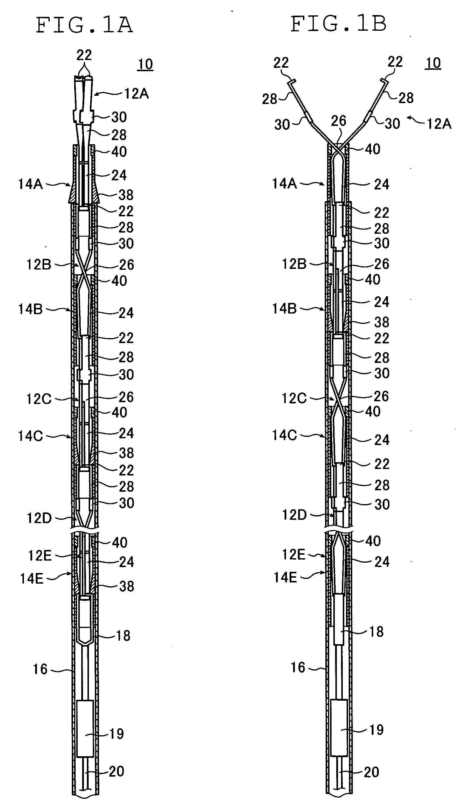
[0045]FIGS. 1A and 1B are sectional views of a clipping device 10 according to Embodiment 1 of the present invention, and FIG. 1B is a diagram as seen from an angle differing from FIG. 1A by 90 degrees.

[0046]The clipping device 10 is a magazine type clipping device in which clips can be used in succession and which has a plurality of clips 12 (12A, 12B, 12C, 12D, and 12E), a dummy clip 18 connected to the rearmost clip 12D, a manipulating wire 20 connected to the dummy clip via a connecting member 19, and connection rings 14 (14A, 14B, 14C, 14D, and 14E) covering the engagement portions of the adjacent clips 12 to maintain the clips 12 in the connected state, with those components being fitted into a sheath 16. FIGS. 1A and 1B illustrate an initial state immediately before the start of clipping manipulation by the foremost clip 12.

[0047]One clip 12 and one connection ring 14 corresponding to the clip 12 form one endoscopic bleeding stop clip member, and the clipping device 10 includ...

embodiment 2

[0188]Next, Embodiment 2 of the present invention is described. While the clipping device of Embodiment 1 described above is of the magazine type, the clipping device of Embodiment 2 is of a single-loader type. FIG. 11 illustrates a retaining ring 48 used in the clipping device of Embodiment 2.

[0189]The retaining ring 48 includes a clamping portion 40 similar to the clamping portion 40 of the connection ring 14 used in Embodiment 1, and a retaining portion 44 formed by shortening the retaining portion 42 and substantially formed solely of the first region 32. The construction and operation of the clamping portion 40 are the same as those of the clamping portion 40 of the connection ring 14 of Embodiment 1, and the construction and operation of the retaining portion 44 are the same as those of the first region 32 of the retaining portion 42 of the connection ring 14 of Embodiment 1.

[0190]FIGS. 12A through 12D illustrate a clipping device 46 according to Embodiment 2. FIGS. 12B and 12...

embodiment 3

[0196]Instead of the connection rings 14 of the clipping devices 10 of Embodiment 1, it is possible to use a connection ring 114 as illustrated in FIGS. 13A through 13C.

[0197]The connection ring 114 is of the same construction as the connection ring 14 of Embodiment 1 except that two slits 46 are formed in a second region 134 of a retaining portion 142. That is, the connection ring 114 includes the metal clamping portion 40 and the resin retaining portion 142, and the retaining portion 142 has a first region 32 and a second region 134, with the second region 134 having the slits 46 cut from the proximal end thereof at positions opposed to each other.

[0198]The slits 46 are formed at two positions deviated from the skirt portions 38 by 90 degrees so as to be shallower than the upper end of the second region 134. In other words, the slits 46 are provided at positions deviated by 90 degrees from the direction in which the clips 12 retained by the second region 134 are diverged.

[0199]Due...


PUM


Abstract

A clipping device comprises: a clip loaded into a forward end portion of a sheath; a manipulating wire connected to a rear end of the clip; and a retention ring fitted onto the clip and fitted into the sheath so as to be capable of advancing and retreating. The retention ring includes: a resin retaining portion which has two or more skirt portions which, when being situated inside the sheath, are closed inwardly by being pressed by an inner wall of the sheath and which, when being situated outside of a forward end of the sheath, are opened in a width larger than an inner diameter of the sheath to prevent retreat into the sheath, and a metal clamping portion arranged on a forward end side of the retaining portion and, when being situated on a forward end side of the clip, abutting the clip to clamp it.

Description

BACKGROUND OF THE INVENTION[0001]The present invention relates to an endoscopic clipping device used to effect stopping of bleeding, closing of a puncture, etc. in a living body or the like.[0002]In an endoscopic clipping device, a clip is caused to protrude from a distal end of an endoscope inserted into a living body, and a portion to be ligated, such as a bleeding portion or a portion from which a lesioned tissue has been removed is pinched by the clip, thereby stopping the bleeding or closing the puncture. A conventional clipping device has a clip whose distal end is open, and a clamping part for closing the clip to effect fastening, with the clip being closed by causing the clamping part to advance with respect to the open clip.[0003]For example, JP 2002-272751 A discloses a construction in which a clip clamping ring is attached to a rear end portion of a clip and in which the clip is pulled with respect to the clip clamping ring to thereby draw the clip into the clip clamping ...

Claims


Application Information

Patent Timeline
IPC IPC(8): A61B17/10
CPCA61B17/1285A61B17/122
Inventor CUI, SHENGFU
Owner FUJIFILM CORP
Learn More