Radio communication apparatus

a radio communication and apparatus technology, applied in the field of radio communication systems, can solve the problems of system limitations, product size requirements that are often subject to conflicting requirements, and limitations of conventional wireless transceiver products

Inactive Publication Date: 2009-09-10
NETGEAR INC
View PDF27 Cites 7 Cited by
  • Summary
  • Abstract
  • Description
  • Claims
  • Application Information

AI Technical Summary

Problems solved by technology

For several reasons, such products are often subject to conflicting size requirements.
The limitations of conventional wireless transceiver products can be illustrated with particular respect to current wireless adapter systems, which provide plug-in wireless communications capabilities to a host system such as a laptop computer.
The wireless adapter can also comprise one or more movable antenna portions which can increase design flexibility, but such systems are still constrained by limitations such as described below.
A problem with the above design is that the radio antenna structure must be more or less completely contained within the wireless transceiver package.
Furthermore, the effective bandwidth of antennas constructed in this manner may be limited.
However, such grounded components can also operate for example as de-tuning and de-sensing elements for the antenna, thereby compromising antenna operation.
Another challenge for radio communications systems is in simultaneously satisfying demands for increased data transfer rates, smaller and more inexpensive systems, and increased complexity.

Method used


Image

  • Radio communication apparatus
  • Radio communication apparatus
  • Radio communication apparatus

Examples


example 1

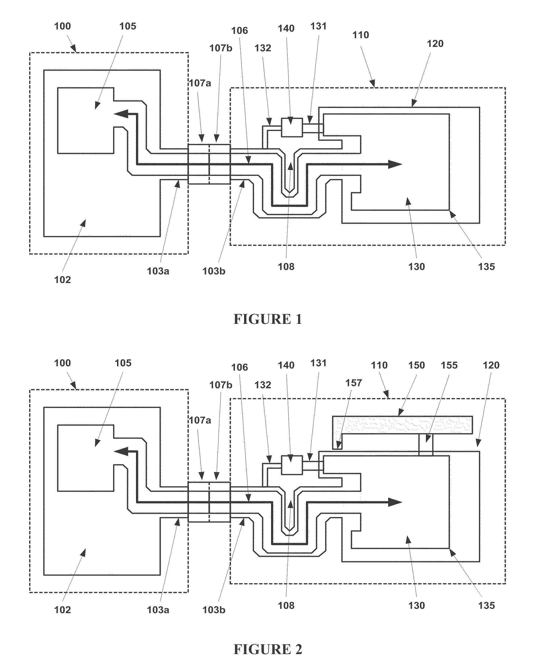
[0080]FIGS. 1 and 2 illustrate a radio communication apparatus package 110 coupled to a host system 100 according to one embodiment of the present invention. The host system 100 can be, for example, a personal computer or portion thereof, having an integral electronics system 105 and a host electromagnetic body or ground plane 102. The host system also includes a USB or similar connection port having a mating section 107a which connects to a corresponding mating section 107b of the apparatus package 110. These two mating sections can connect the host system 100 and the apparatus package 110 during operation. A conductive enclosure or shielding 103a is electrically connected to the ground plane 102 and extends from the host system 100 to the apparatus package 110 by virtue of electrical connection through external shielding of the two mating sections 107a and 107b and the shield 103b. The conductive enclosure 103a and 103b surrounds at least a portion of an electronics pathway 106 wh...

example 2

[0089]FIGS. 4A and 4B illustrate the layout of the coupling element 420 coupling a host system 400 and an antenna body 410 according to one embodiment of the present invention. In the present embodiment, the coupling element 420 includes a mating USB connection having a shielded outer portion 425 connected to a ground plane of the host system 400. A conductive enclosure 430 is coupled to the shielded outer portion 425 such that a signal pathway comprising USB differential data, power and ground lines can be routed from the host system to the antenna body through the shielded outer portion 425 and the conductive enclosure 430. The conductive enclosure 430 includes a wave trap, such as the “U”-shaped wave trap 435, or one of the alternative wave traps illustrated in FIG. 6, which is configured to substantially impede the flow of radio frequency energy or current between the host system 400 and the antenna body 410.

[0090]For electromagnetic coupling of the antenna body 410 and the host...

example 3

[0091]FIG. 5 illustrates two radio bodies 500 and 550 coupled together to form a two-element or “dipole” antenna according to one embodiment of the present invention. The dipole antenna is characterized in that each of two radiating bodies 510 and 560 are driven by a local inclusive electronics system 520 and 570, respectively, the electronics systems communicating through a signal pathway 544 of a coupling element 546, the coupling element 546 configured to substantially impede electromagnetic coupling of the radiating bodies directly through the coupling element 546 by incorporation of a wave trap 548 with the coupling element 546.

[0092]Coupling between the radiating bodies and / or the electronics systems can be provided using a matching element 530 configured to substantially provide a desired electromagnetic coupling, for example as is required to operate the two radiating bodies 510 and 560 as a dipole antenna, and to match the impedance of the radiating bodies with transmission...


PUM


Abstract

The present invention provides a radio communication apparatus for use with a host system. The host system includes an electromagnetic body which acts as a ground plane or counterpoise for the radio communication apparatus. The apparatus comprises an electronics system coupled to the host system, a radio module including a radio electromagnetic body and optionally a radio electronics system, a signal pathway operatively coupling the electronics system with the radio module, and a conductive enclosure. The conductive enclosure provides electromagnetic isolation of the signal pathway. The conductive enclosure is further configured, by inclusion of a wave trap, to impede electromagnetic coupling between the radio electromagnetic body and the host electromagnetic body via the conductive enclosure.

Description

RELATED APPLICATIONS[0001]This application claims priority to U.S. Provisional Patent Application No. 61 / 032,814 filed Feb. 29, 2008 and entitled “Radio Communication Apparatus.” The complete disclosure of the above-identified priority application is hereby fully incorporated herein by reference.FIELD OF THE INVENTION[0002]The present invention pertains in general to radio communications systems and in particular to radio transceiver packages for coupling with an external system.BACKGROUND OF THE INVENTION[0003]In wireless, radio communications, many transceiver products are available which package a radio antenna along with the electronics necessary for its operation to provide convenient wireless, radio communications capabilities. For several reasons, such products are often subject to conflicting size requirements. For example, wireless transceivers for use with cellular telephones or personal computing devices must be conveniently sized for portability and user experience. Howe...

Claims


Application Information

Patent Timeline
IPC IPC(8): H04L5/16H04M1/00H05K7/10
CPCH01Q1/22H01Q1/243H01Q9/0407H01Q9/24H01Q13/10H04B15/02H04B5/0081H04B7/10H05K9/0056H01Q1/50H01Q21/28H04B5/26
Inventor NYSEN, PAUL A.YEN, CHIH-CHUAN
Owner NETGEAR INC
Why Eureka
Try Eureka