
Wide-Angle Compound-Eye Imaging Device

a compound-eye imaging and wide-angle technology, applied in the field of wide-angle compound-eye imaging devices, can solve the problems of difficult manufacturing of compound-eye imaging devices, limited range of viewfinders, and and achieve the effect of easy production, increased cost, and easy acquisition of distortion-free wide-angle capture images

Inactive Publication Date: 2009-09-10
FUNAI ELECTRIC CO LTD
View PDF6 Cites 15 Cited by
  • Summary
  • Abstract
  • Description
  • Claims
  • Application Information

AI Technical Summary

Benefits of technology

[0008]An object of the present invention is to provide a wide-angle compound-eye device which makes it possible to easily obtain a distortion-free wide-angle capture image with a large picture angle in a direction perpendicular to the wide-angle direction without making it difficult to manufacture it or increasing its cost.
[0010]Due to the optical path modifying means placed on the light entrance side of the optical lenses, a distortion-free wide-angle capture image with a large picture angle in a direction perpendicular to the wide-angle direction can be easily obtained. In addition, since this wide-angle compound-eye imaging device does not require the use of a special lens such as a combined lens, it can be easily manufactured without increasing its cost.
[0011]Preferably, the multiple optical lenses comprise: left and right optical lenses placed on a line parallel to the wide-angle direction (such line being hereafter referred to as left-right direction line) for collecting light entering in left and right angular ranges in the capture range; and an optical lens (hereafter referred to as center optical lens) placed in a position vertically distant from the left and right optical lenses for collecting light entering in a center angular range in the capture range. The optical path modifying element is a toroidal lens comprising: a first curved surface having a curvature with a curvature axis parallel to the left-right direction line; and a second curved surface having a curvature with a curvature axis which is perpendicular to the left-right direction line and passes through the center optical lens. This makes it possible to obtain a distortion-free wide-angle capture image with a large picture angle in a direction perpendicular to the wide-angle direction even if the optical lenses are placed at apexes of a triangle.
[0012]Further preferably, the optical path modifying element is integrally assembled with a housing of the wide-angle compound-eye imaging device so as to serve as a protecting cover for the optical lenses. This makes it possible to achieve a compact design of the entire housing, and hence, of the entire wide-angle compound-eye imaging device.

Problems solved by technology

However, the picture angle from up to down, which is in a direction perpendicular to the wide-angle direction, is limited by the capture angle (i.e. convergence angle) specific to each optical lens.
However, in a compound-eye imaging device, each optical lens is normally formed very small (as small as a few millimeters, for example), so that the provision of the combined lens makes it difficult to manufacture the compound-eye imaging device, and increases its cost.
If, on the other hand, each optical lens is formed large, the size or volume of the resultant compound-eye imaging device becomes large.
This reduces the advantage of small size which the compound-eye imaging device basically has.
However, this does not solve the problems described above.

Method used


Image

  • Wide-Angle Compound-Eye Imaging Device
  • Wide-Angle Compound-Eye Imaging Device
  • Wide-Angle Compound-Eye Imaging Device

Examples


Embodiment Construction

[0026]Embodiments of the present invention, as best mode for carrying out the invention, will be described hereinafter with reference to the drawings. The present invention relates to a wide-angle compound-eye imaging device. It is to be understood that the embodiments described herein are not intended as limiting, or encompassing the entire scope of, the present invention. Note that like parts are designated by like reference numerals, characters or symbols throughout the drawings.

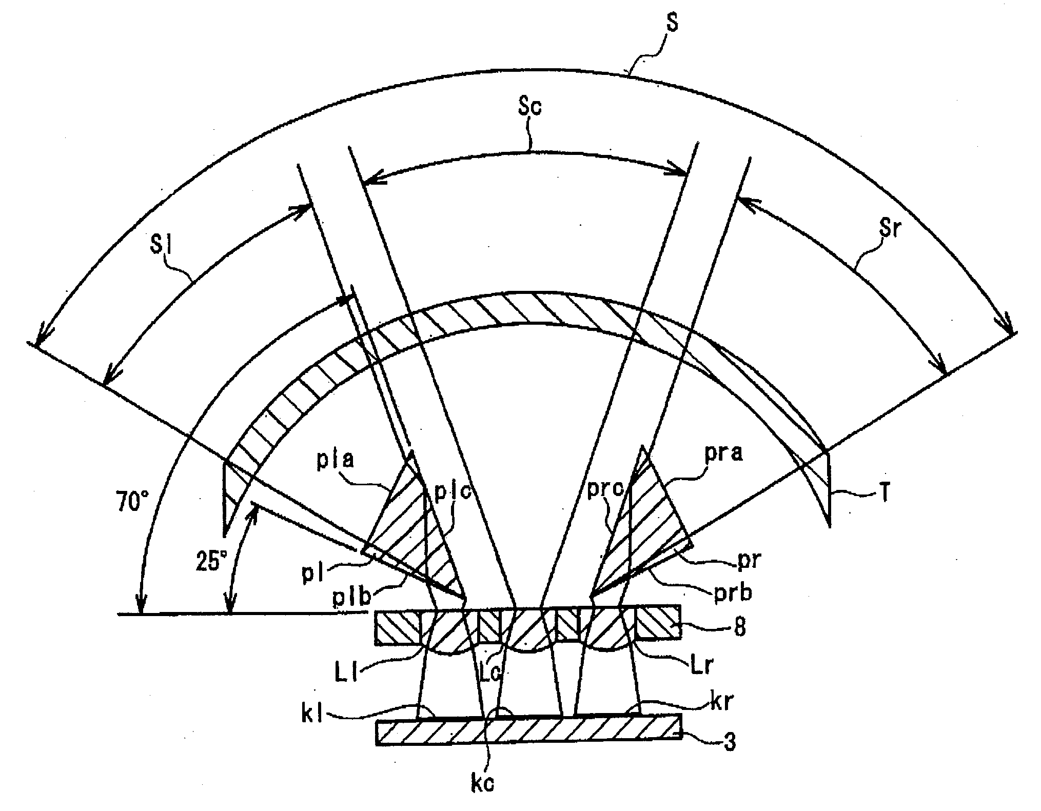
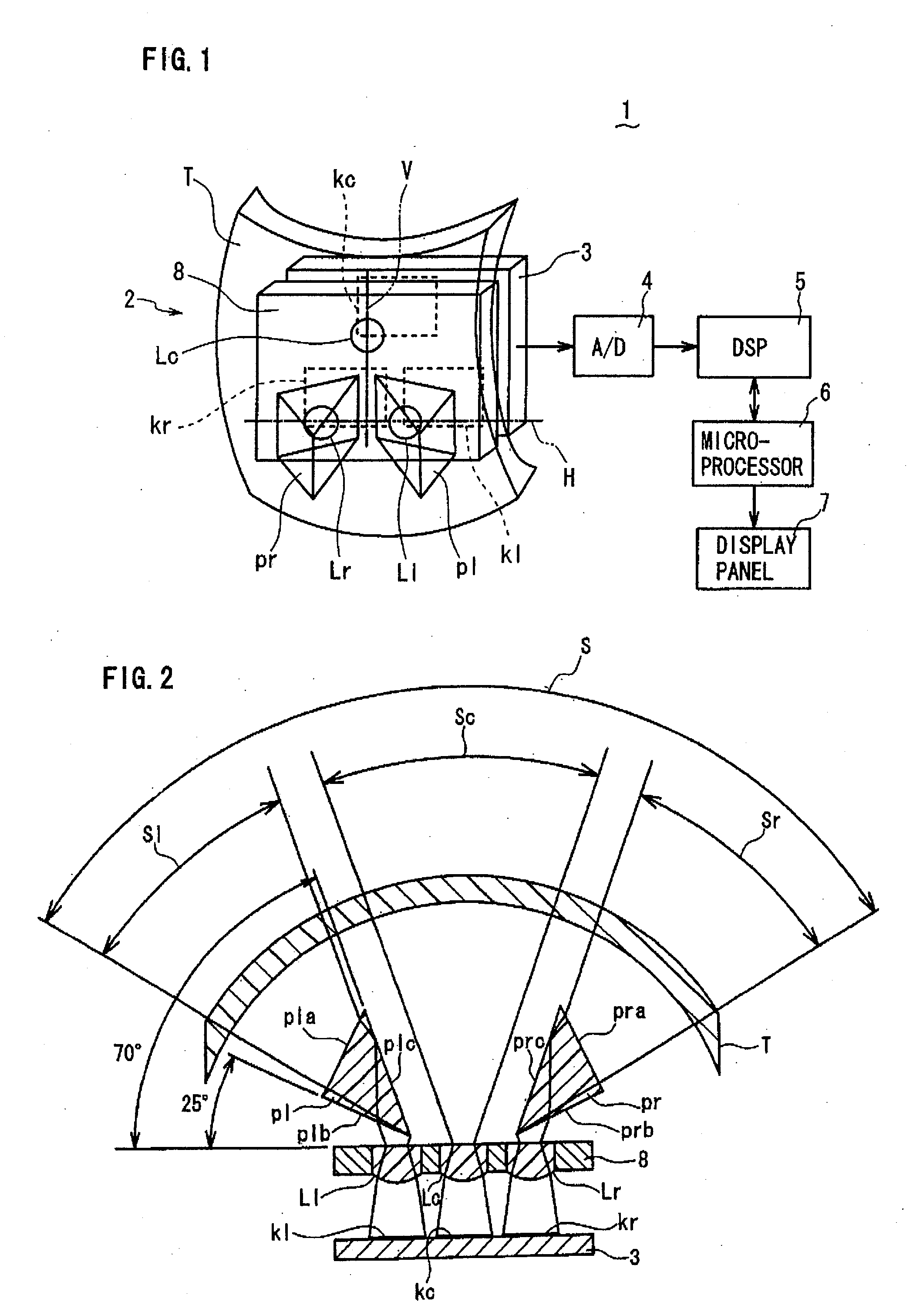
[0027]Referring to FIG. 1 to FIG. 11, a wide-angle compound-eye imaging device 1 according to an embodiment of the present invention will be described. FIG. 1 is a schematic perspective view of the wide-angle compound-eye imaging device 1 including an optical lens system 2 with a processing circuit, in block diagram form, for signal processing and display, while FIG. 2 is a schematic horizontal cross-sectional view of the optical lens system 2. As shown in FIG. 1 and FIG. 2, the optical lens system 2 of t...


PUM


Abstract

A center lens for collecting light in a center range and left / right lenses for collecting light in left / right ranges are supported in one plane to form center and left / right unit images. A microprocessor combines the unit images into a wide-angle image. The left / right optical lenses are placed on left-right direction line parallel to the wide-angle direction, while the center lens is placed distant from the left / right lenses above the direction line. Prisms are placed in front of the left / right lenses, and a toroidal lens to vertically modify the light path for light convergence onto each lens is placed in front of the prisms. The toroidal lens has a vertically curved surface having an axis coinciding with the direction line, and a horizontally cured surface having an axis coinciding with a vertical line passing through the center lens. This device can obtain a wide-angle image with a vertically large picture angle.

Description

BACKGROUND OF THE INVENTION[0001]1. Field of the Invention[0002]The present invention relates to a wide-angle compound-eye imaging device.[0003]2. Description of the Related Art[0004]A wide-angle compound-eye imaging device with a wide field of view is known in which light entering in a wide-angle capture range is collected by multiple optical lenses in predetermined divided or shared angular ranges in the direction from left to right in the wide field of view or wide-angle capture range (hereafter referred to simply as wide-angle direction), and unit images formed by the optical lenses in the respective angular ranges are combined into a wide-angle capture image as disclosed in e.g. Japanese Laid-open Patent Publication 2007-288569. In such compound-eye imaging device, the optical lenses are placed from left to right (left, center and right) in the wide-angle direction, while a prism is placed in front of each left and right optical lens to share each left and right angular range t...

Claims


Application Information

Patent Timeline
Patent Type & Authority Applications(United States)
IPC IPC(8): G02B13/06
CPCG02B13/06
Inventor TOYODA, TAKASHINAKAO, YOSHIZUMIIMAHORI, YOSHIMASA
Owner FUNAI ELECTRIC CO LTD
Learn More