
Liquid crystal display and method of driving liquid crystal display

a technology of liquid crystal display and capacitor line, which is applied in the direction of instruments, static indicating devices, etc., can solve problems such as complex circuit configuration, and achieve the effect of low power consumption and no damage to display quality

Active Publication Date: 2009-08-27
EPSON IMAGING DEVICES CORP +1
View PDF3 Cites 8 Cited by
  • Summary
  • Abstract
  • Description
  • Claims
  • Application Information

AI Technical Summary

Benefits of technology

[0009]An advantage of some aspects of the invention is that it provides a liquid crystal display and a method of driving a liquid crystal display capable of achieving low power consumption without damaging display quality.
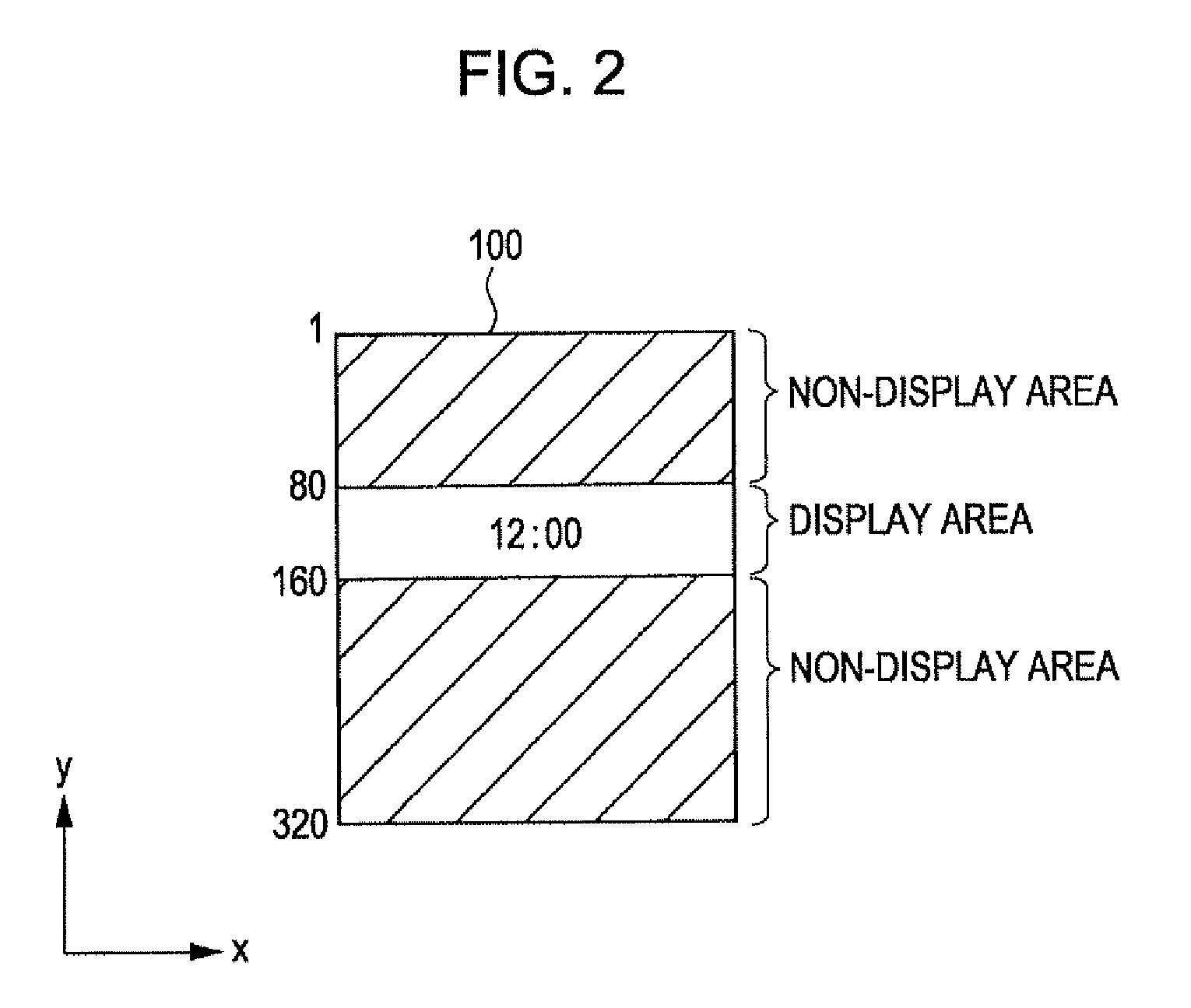
[0011]With this configuration, storage capacitor line driving can be activated in the display area, and storage capacitor line driving can be stopped in the non-display area. Therefore, the liquid crystal display can be driven with low power consumption. In addition, the display area is changed (a transition sequence is executed) depending on the frame inversion signal (frame polarity). For this reason, in a first frame when a transition sequence is executed, defective display can be suppressed. As such, low power consumption can be achieved without damaging display quality.
[0013]With this configuration, a frame in which a transition sequence is executed can be limited, and thus in a first frame when a transition sequence is executed, it is possible to suppress the occurrence of the problem of storage capacitor line driving being stopped in the display area and storage capacitor line driving being activated in the non-display area. As a result, defective display can be reliably suppressed.
[0021]With this configuration, in the non-display area of the partial display mode, the common potential is supplied to perform image display (non-display), and a so-called source write operation to write display signals from the source line driving circuit in the pixels can be stopped. Therefore, in the partial display mode which requires low power consumption, low power consumption can be achieved.
[0025]With this configuration, it is possible to provide a method of driving a liquid crystal display that can achieve low power consumption without damaging display quality,

Problems solved by technology

As a result, the circuit configuration becomes complicated.

Method used


Image

  • Liquid crystal display and method of driving liquid crystal display
  • Liquid crystal display and method of driving liquid crystal display
  • Liquid crystal display and method of driving liquid crystal display

Examples


Embodiment Construction

[0037]Hereinafter, an embodiment of the invention will be described with reference to the drawings.

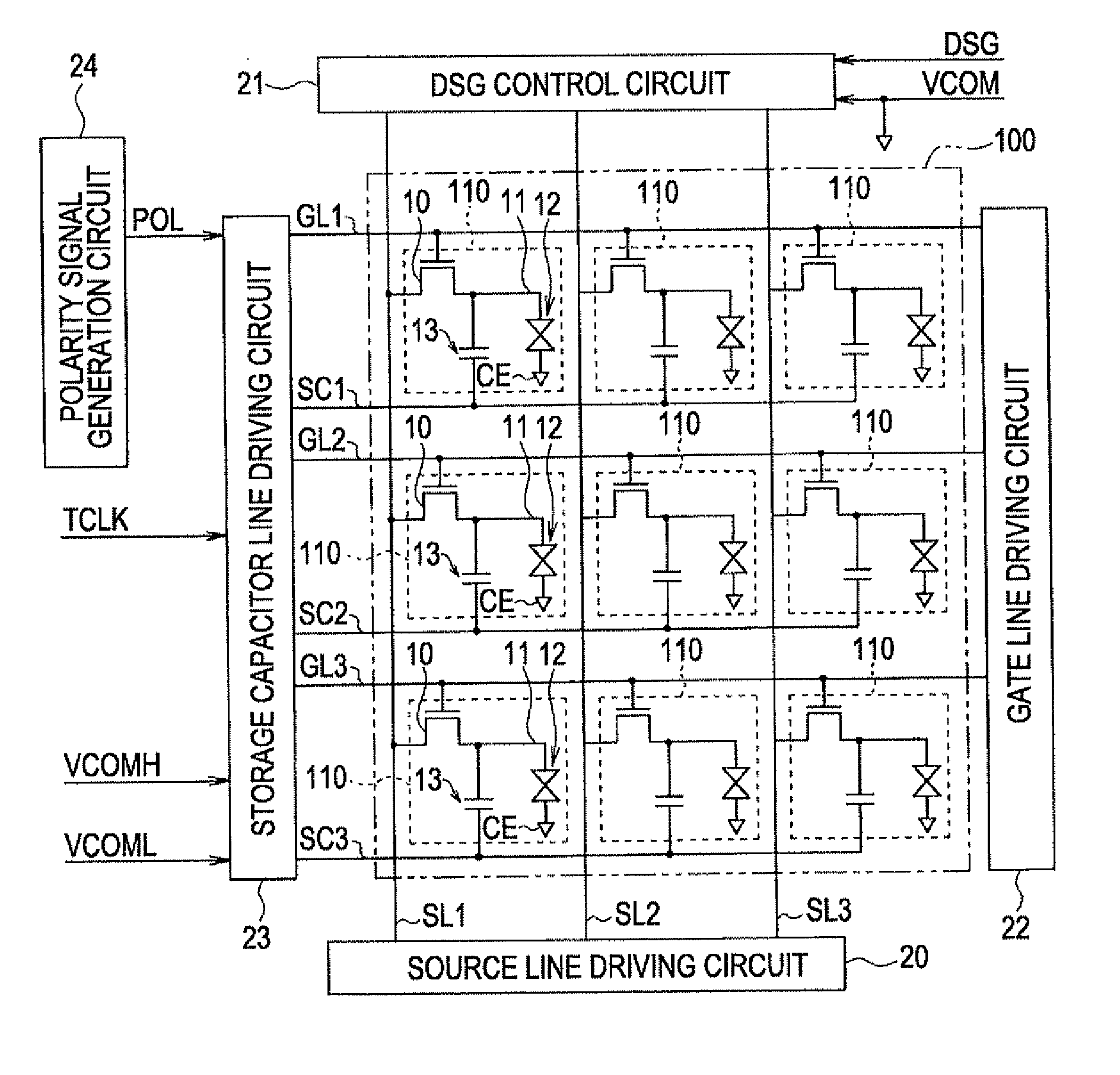
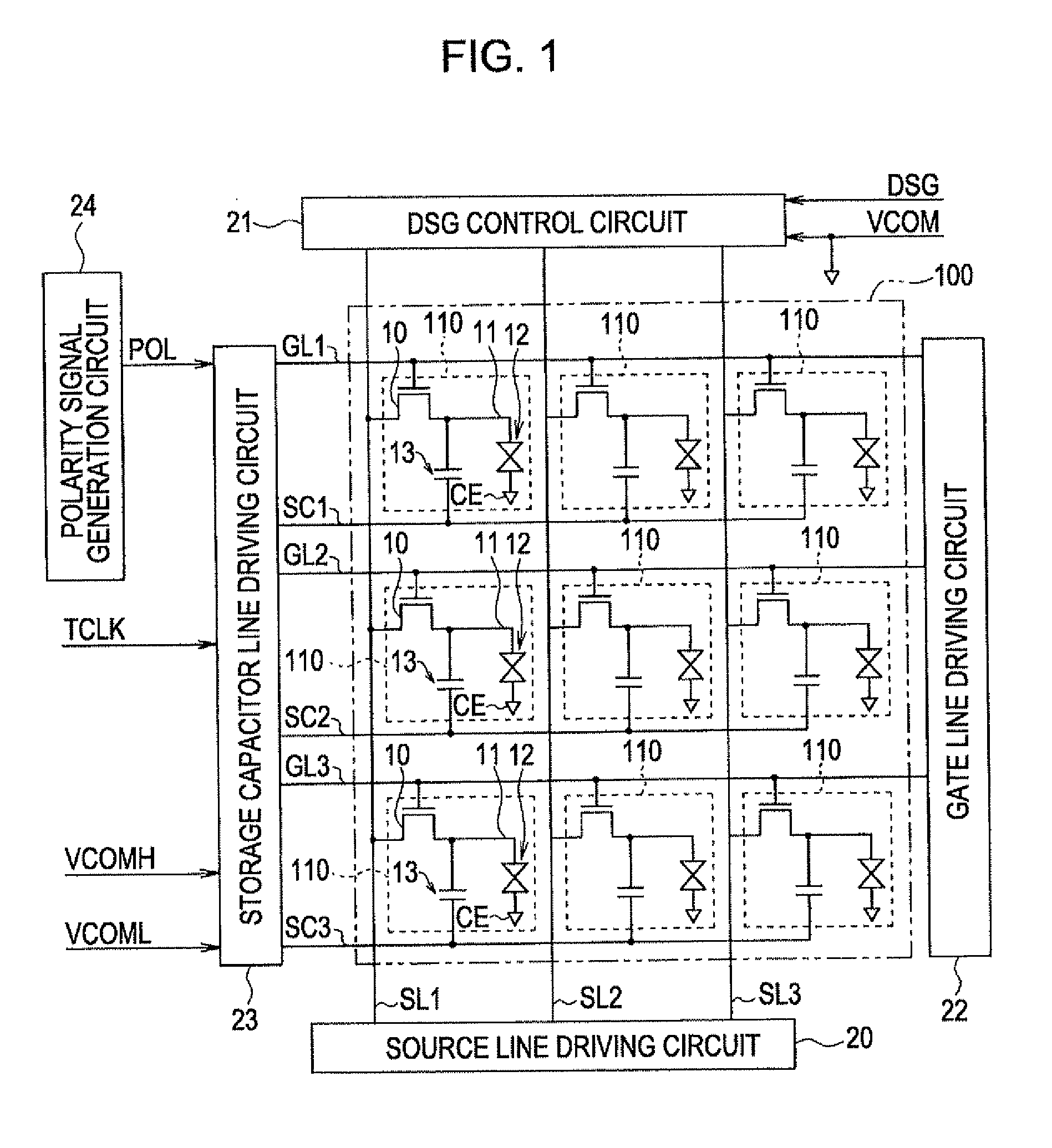
[0038]FIG. 1 is a block diagram showing the configuration of a liquid crystal display according to this embodiment.

[0039]As shown in FIG. 1, a liquid crystal display has a pixel area 100. A source line driving circuit20, a DSG control circuit 21, a gate line driving circuit 22, a storage capacitor line driving circuit 23, and a polarity signal generation circuit 24 are arranged around the pixel area 100. It is assumed that the liquid crystal display of this embodiment uses a storage capacitor line driving method.

[0040]The pixel area 100 has a plurality of pixels 110, and 320 rows of gate lines GL and 240 columns of source lines SL extending in a row (X) direction and a column (Y) direction, respectively. The pixels 110 are arranged at intersections between the gate lines GL of the first to 320th rows and the source lines SL of the first to 240th columns. Storage capacitor lines SC exte...


PUM


Abstract

A liquid crystal display selectively operates in one of a full screen display mode, in which the full screen of the display panel is set as a display area, and a partial display mode, in which a partial area in the full screen is set as a display area and a remaining area is set as a non-display area. The liquid crystal display includes a plurality of gate lines, a plurality of source lines, a plurality of storage capacitor lines that are provided to correspond to the plurality of gate lines, a plurality of pixels that are provided at intersections between the plurality of gate lines and the plurality of source lines, a polarity signal generation circuit that generates a polarity signal corresponding to a frame inversion signal to be repeatedly alternately inverted between a first level and a second level different from the first level for each frame in the display area, and generates a polarity signal corresponding to a fixed signal fixed at one of the first level and the second level in the non-display area, a storage capacitor line driving circuit that changes the potentials of the storage capacitor lines depending on the polarity signal generated by the polarity signal generation circuit, and a control circuit that changes the display area at a timing according to the frame inversion signal.

Description

BACKGROUND[0001]1. Technical Field[0002]The present invention relates to a storage capacitor line driving liquid crystal display and a method of driving a liquid crystal display.[0003]2. Related Art[0004]A storage capacitor line driving method is known as one of driving methods of liquid crystal displays. This driving method is configured such that a storage capacitor is provided between a storage capacitor line and a pixel electrode. After a display signal is written in the pixel electrode, if the potential of the storage capacitor line is changed, the potential of the pixel electrode is changed to positive or negative. With this configuration, the dynamic range of the display signal can be reduced, and the liquid crystal display can be driven with low power consumption. Such a storage capacitor line driving liquid crystal display is disclosed in JP-A-2002-196358.[0005]A partial display method is known as one of display methods of liquid crystal displays. In this display method, a ...

Claims


Application Information

Patent Timeline
IPC IPC(8): G09G3/36
CPCG09G3/3614G09G3/3648G09G2310/06G09G3/3666G09G3/3655
Inventor TAJIRI, KENICHI
Owner EPSON IMAGING DEVICES CORP
Learn More