
Heat staked shelf

a shelf and heat-staking technology, applied in the field of heat-staking shelves, can solve the problems of affecting the safety of refrigerator shelving, affecting the safety of storage shelves, and easy to harbor bacteria, mold and other materials

Inactive Publication Date: 2009-08-27
MCMILLIN MATTHEW J +1
View PDF19 Cites 33 Cited by
  • Summary
  • Abstract
  • Description
  • Claims
  • Application Information

AI Technical Summary

Benefits of technology

"The invention is a shelving assembly for use in refrigerators and other articles. The assembly includes a shelf panel made of glass and a plastic rim that is secured to the shelf panel. The plastic rim has heat stake ribs and pads that provide retention and support for the shelf panel. The securing means can include heat stake ribs and pads that are heated and made pliable, allowing them to secure the shelf panel. The plastic rim can also have a groove for adhesive, and the assembly can also include a slot for adhesive. The technical effects of the invention include improved retention and support for the shelf panel, as well as improved leak-proof sealing between the plastic rim and the shelf panel."

Problems solved by technology

In addition to these design features, one problem which arises with respect to refrigerator shelving relates to spills.
If spills are allowed to build up, they can readily harbor bacteria, mold and other materials which may contaminate food stuffs and the like.

Method used


Image

  • Heat staked shelf
  • Heat staked shelf
  • Heat staked shelf

Examples


first embodiment

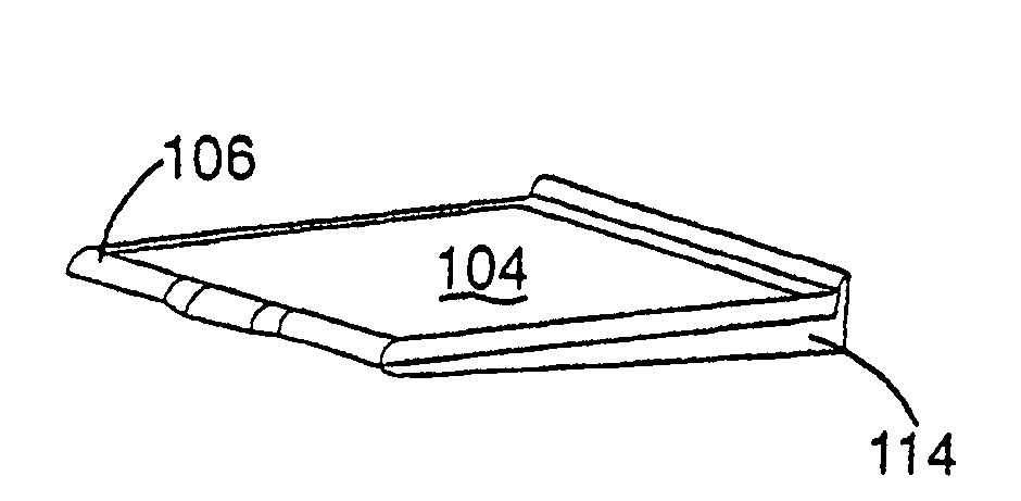
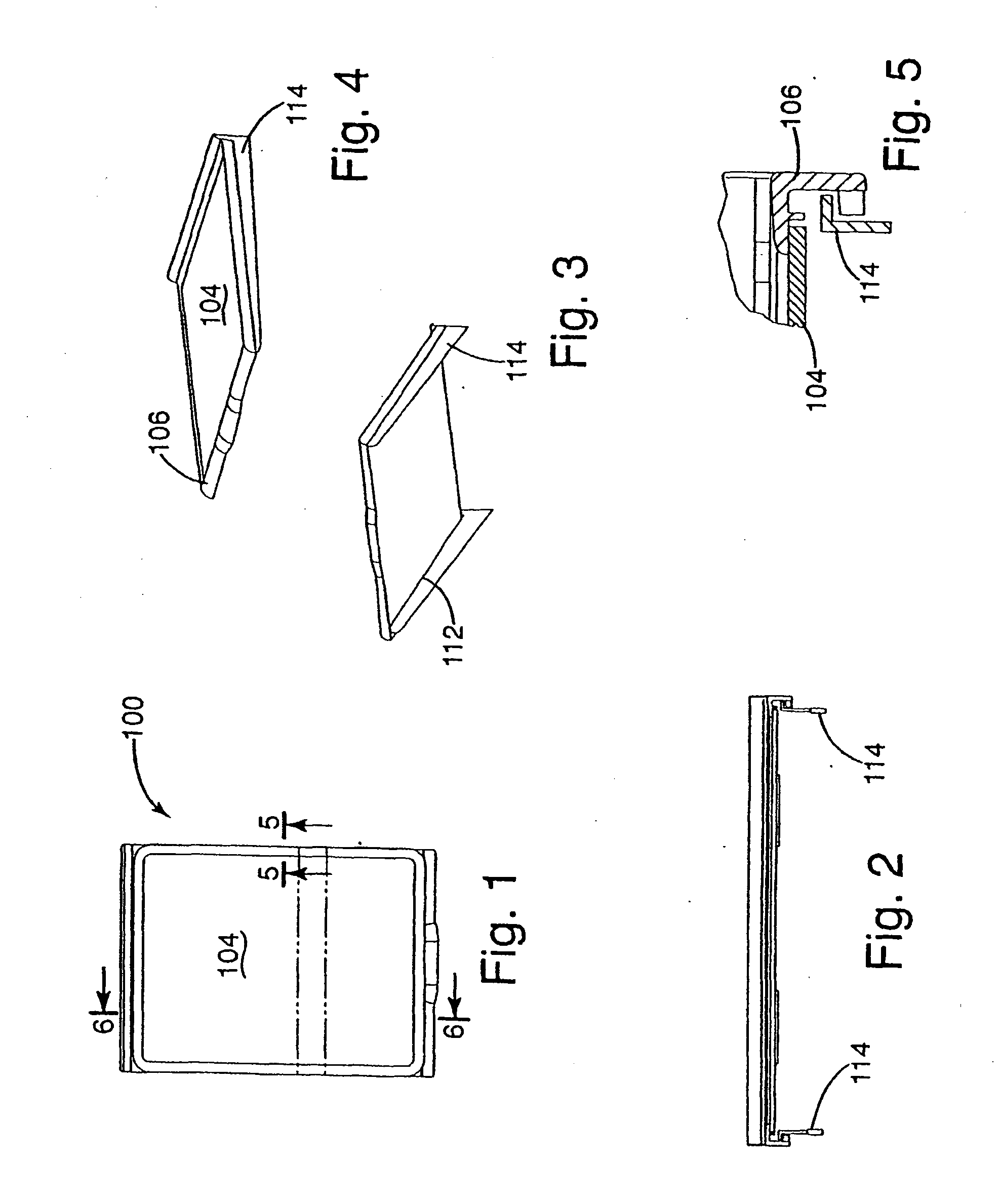
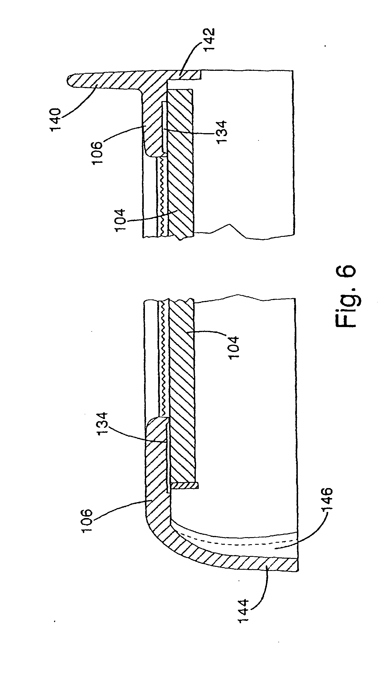
[0073]Turning to the drawings, a shelving assembly in accordance with the invention that will be described is a shelving assembly 100 as illustrated in plan view in FIG. 1, and as further illustrated in FIGS. 2-9. Referring specifically to FIGS. 1-9, the shelving assembly 100 includes a cantilever or metal frame 102 (see FIG. 8). Although this particular embodiment of a shelving assembly in accordance with the invention as illustrated in FIGS. 1-9 utilizes a metal frame 102, it should be emphasized that other embodiments of shelving assemblies in accordance with this invention may consist of a shelving assembly without a metal frame 102. Such an assembly is shown, for example, in the shelving assembly in accordance with the invention as illustrated in FIGS. 13-19. Such an embodiment will be described in subsequent paragraphs herein. Returning to FIGS. 1-9, the metal frame 102 is used in part to support a glass shelf or glass shelf panel 104. In addition, the metal frame 102 is also ...

second embodiment

[0082]a shelving assembly in accordance with the invention is illustrated in part as shelving assembly 200 in FIG. 10. For purposes of clarity and brevity, the entirety of the shelf assembly 200 is not illustrated. The shelf assembly 200 is substantially similar in design and construction to shelf assembly 100 previously described with respect to FIGS. 1-9. The distinctions between shelf assembly 100 and shelf assembly 200 are primarily shown in FIG. 10, which is similar in perspective and content to FIGS. 5 and 7 associated with shelf assembly 100. More specifically, with shelf assembly 200, a metal frame is provided which includes a sideplate 214. The sideplate includes an outwardly projecting tab 228 at its upper portion. The outwardly projecting tab 228 is integral with the sideplate 214. The shelving assembly 200 further includes a plastic rim 206, similar in structure and function to the plastic rim 106 also previously described with respect to FIG. 7. The plastic rim 206 incl...


PUM


Abstract

A shelving assembly (920) is disclosed, with the shelving assembly (920) including a series of heat stake ribs (926). The ribs (926) may be hot formed and made pliable so as to be flexed for purposes of providing additional retention and support to a glass shelf panel (928). The glass shelf panel (928) is also secured to a plastic rim (922). Heat stake pads (942) may be utilized with the heat stake ribs (926). The heat stake ribs (926) may be deformed against the corresponding heat stake pads (942) so as to provide support for the glass shelf panel (928).

Description

CROSS-REFERENCE TO RELATED APPLICATIONS[0001]This application is a continuation of U.S. patent application Ser. No. 10 / 514,199 filed Jul. 7, 2005, which is a continuation-in-part of U.S. patent application Ser. No. 10 / 375,632 filed 27 Feb., 2003 and an International Patent Application No. PCT / US03 / 02045 filed 24 Jan., 2003. The United States patent application and the International Application claim priority of U.S. Provisional patent application Ser. No. 60 / 351,917, filed 25 Jan., 2002, and U.S. Provisional Patent Application Ser. No. 60 / 361,464, filed 4 Mar., 2002.STATEMENT REGARDING FEDERALLY SPONSORED RESEARCH OR DEVELOPMENT[0002]Not applicable.REFERENCE TO A MICROFICHE APPENDIX[0003]Not applicable.BACKGROUND OF THE INVENTION[0004]1. Field of the Invention[0005]The invention relates to shelving designs which may be adapted for use with refrigerators and other articles employing shelving and, more particularly, shelving having glass supported in part through the use of heat stake...

Claims


Application Information

Patent Timeline
Patent Type & Authority Applications(United States)
IPC IPC(8): F25D23/00F16J15/10A45F5/08A47BA47B96/02A47F5/08A47F7/00F25D11/00F25D25/02
CPCA47B96/062F25D2325/022F25D25/02
Inventor MCMILLIN, MATTHEW J.ROUCH, ERIC
Owner MCMILLIN MATTHEW J
Learn More