
Welding helmet positive air pressuring system and method

a positive air and pressuring technology, applied in the field of welding helmet cooling and filtering systems, can solve the problems of papr systems, a relatively expensive approach to ventilation and cooling, and the heat intensive process of welding,

Active Publication Date: 2009-08-27
ILLINOIS TOOL WORKS INC
View PDF7 Cites 62 Cited by
  • Summary
  • Abstract
  • Description
  • Claims
  • Application Information

AI Technical Summary

Benefits of technology

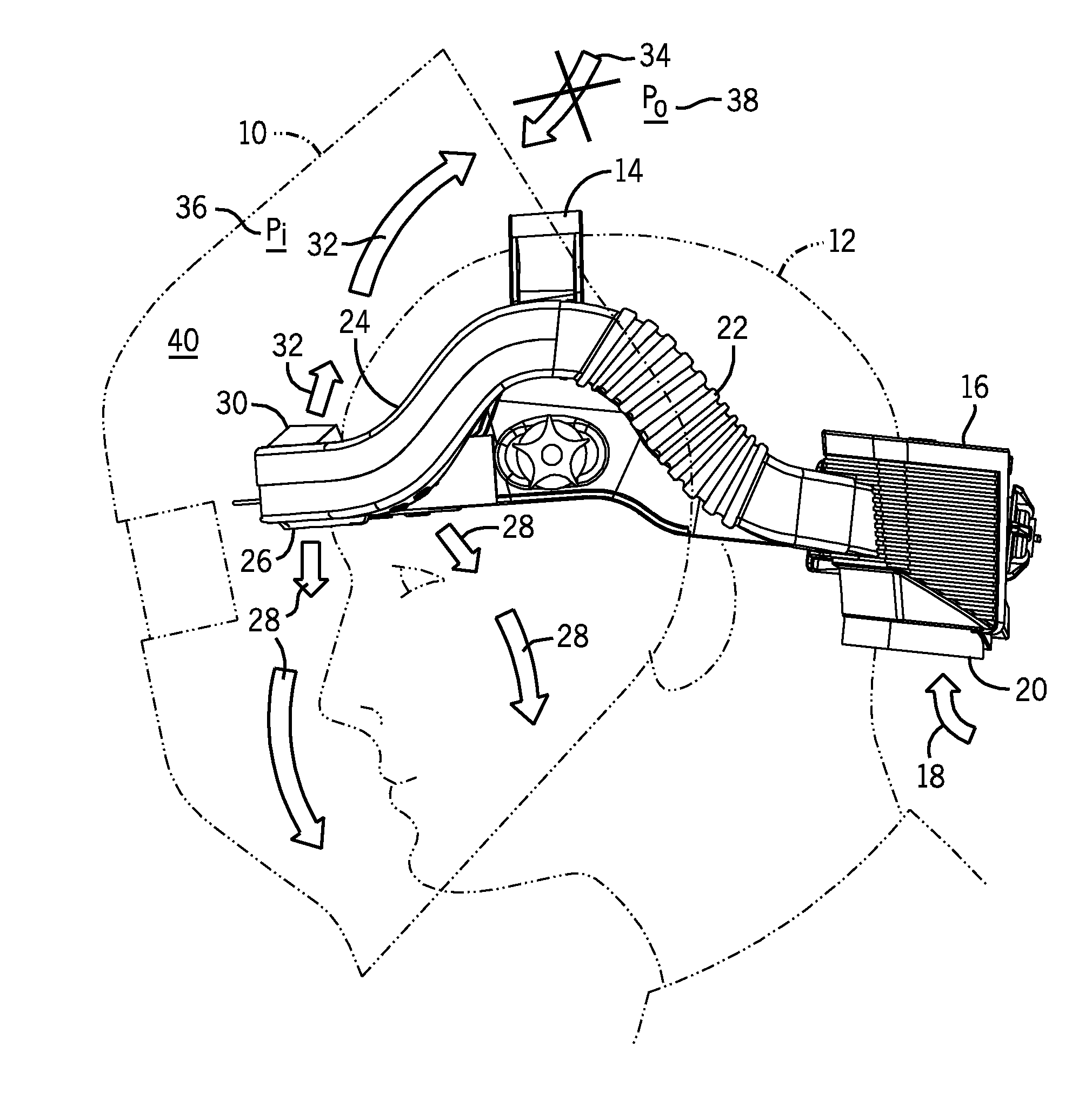
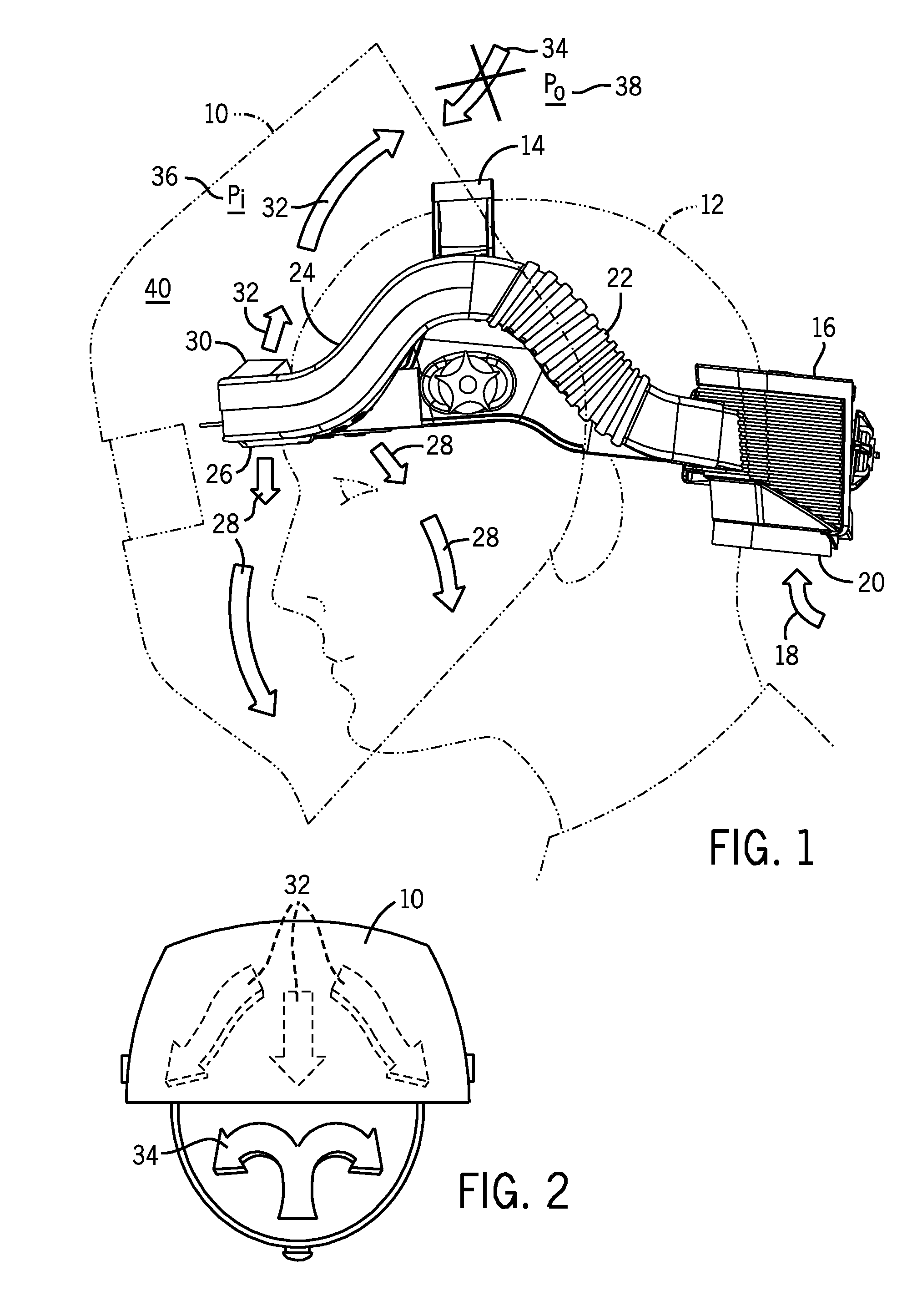
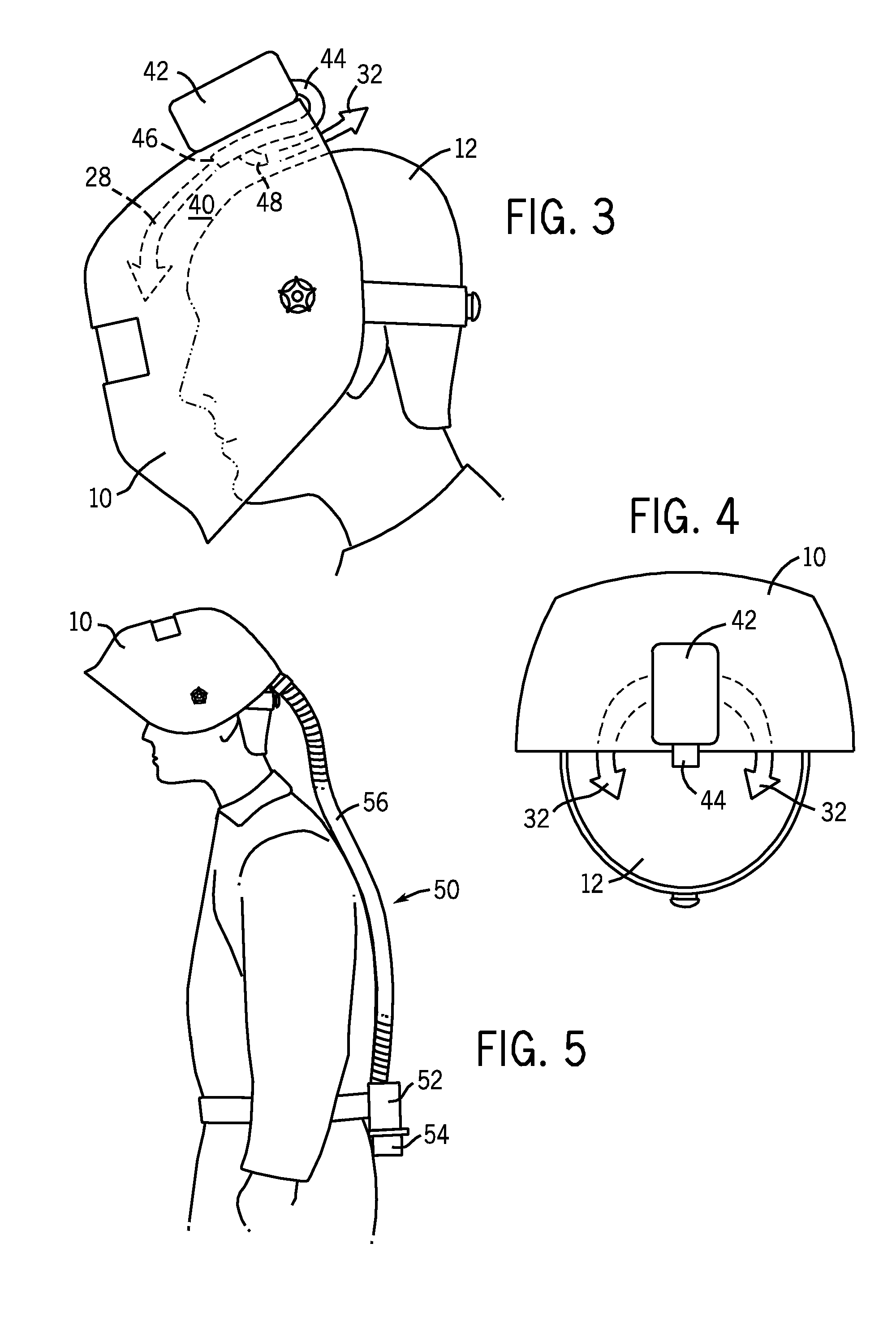
[0006]The present invention provides a novel welding helmet ventilation system designed to respond to such needs. The invention may be adapted to a wide variety of system types, and may reduce or eliminate the need for a shroud or barrier around the head and neck of the welder, of the type used in PAPR systems. In particular, the invention provides a method and system for controlling airflow in a welding helmet. The airflow system provides a forward air stream directed onto the face of the welder and a rearward air stream directed onto the top of the head of the welder and / or toward the back of the head of the welder for the dual purposes of cooling the welder and creating a positive pressure system that excludes external airflow. Certain embodiments may include streams that are filtered, split or redirected via deflectors and conduits to achieve the aforementioned goals.

Problems solved by technology

Welding can be a heat intensive process, especially during the summer months in outdoor locations or in plants without air conditioning or good air circulation.
Furthermore, welding environments contribute fumes and particulates to the locations in which welding is performed.
While some industrial standards exist that require powered air purifying respirator (PAPR) systems, such standards may not apply to all situations in which improved air circulation may be desirable for operator comfort, particularly over extended periods of work.
Moreover, when not required, PAPR systems represent a relatively costly approach to ventilation and cooling.
Further, PAPR systems generally include a shroud or blanket arrangement that covers the head and neck of the welder, which can be cumbersome to don, doff and wear.
Many welding environments may remain quite uncomfortable, particularly over extended periods of welding work, due to lack of sufficient cooling or ventilating air flow, reducing worker productivity and satisfaction.
Where cost permits, welders in less intense environments may opt for a PAPR system, but many are discouraged by the high level of discomfort associated with these bulky systems, as well as the associated costs.

Method used


Image

  • Welding helmet positive air pressuring system and method
  • Welding helmet positive air pressuring system and method
  • Welding helmet positive air pressuring system and method

Examples


Embodiment Construction

[0017]FIG. 1 illustrates an exemplary welding helmet 10 that incorporates an integrated air flow system in accordance with aspects of the invention. The head of the welder 12 may don headgear 14, which contains straps that provide support and stability for the welding helmet 10. An airflow system 16 may be attached to or integrated into the headgear 14 and may generally follow the circumference of the headgear 14. In certain embodiments, the airflow system may be permanently attached to the headgear. In such an embodiment, the headgear itself may serve as part of the air conduit. However, in other embodiments, the airflow system may be affixed to the headgear using mounting brackets or other attachment methods. By generally following the circumference of the headgear 14, the airflow system 16 may be located close to the user's head to promote stability and balance when worn.

[0018]Air 18 may enter the airflow system through an air intake 20 that is located at the rear of the headgear...


PUM


Abstract

A method and system for controlling ventilation in a welding helmet is provided. The invention may be adapted to a wide variety of system types, and may reduce or eliminate the need for a shroud or barrier around the head and neck of the welder, of the type used in PAPR systems. The airflow system includes forward and rearward air streams, directed onto the face of the welder, onto the top of the head of the welder, and toward the back of the head of the welder. The air streams help to cool the welder, provide a fresh source of air for breathing, and create a positive pressure system that reduces or excludes entrainment of contaminated external air into the forwardly directed air flow. Certain embodiments may include streams that are filtered, split or redirected via deflectors and conduits to achieve the aforementioned goals.

Description

CROSS REFERENCE TO RELATED APPLICATIONS[0001]This application is a Non-provisional Patent Application of U.S. Provisional Patent Application No. 61 / 031,130, entitled “Air Quality Neutralization Means In A Helmet Airflow System”, filed Feb. 25, 2008, which is herein incorporated by reference.BACKGROUND[0002]The invention relates generally to cooling and filtering systems for welding helmets.[0003]The invention relates generally to welding helmets, and more particularly to arrangements for controlling the influx of air into a welding helmet.[0004]Welding can be a heat intensive process, especially during the summer months in outdoor locations or in plants without air conditioning or good air circulation. Furthermore, welding environments contribute fumes and particulates to the locations in which welding is performed. While some industrial standards exist that require powered air purifying respirator (PAPR) systems, such standards may not apply to all situations in which improved air ...

Claims


Application Information

Patent Timeline
IPC IPC(8): A61F9/06
CPCA61F9/068
Inventor BECKER, WILLIAM JOSHUADOBSON, KENNETH S.KWOK, KUI-CHIU
Owner ILLINOIS TOOL WORKS INC
Learn More