Chemical mechanical polishing pad
- Summary
- Abstract
- Description
- Claims
- Application Information
AI Technical Summary
Benefits of technology
Problems solved by technology
Method used
Image
Examples
Example
2. EXAMPLES AND COMPARATIVE EXAMPLES
[0110]Chemical mechanical polishing pads according to examples and chemical mechanical polishing pads according to comparative examples were produced, and chemical mechanical polishing was conducted using the chemical mechanical polishing pads. After polishing, the number of scratches caused by each chemical mechanical polishing pad was measured.
2.1. Production of Chemical Mechanical Polishing Pad (Examples 1 to 14 and Comparative Examples 4 and 5)
[0111]72.8 parts by mass of 1,2-polybutadiene (“JSR RB830” manufactured by JSR Corporation) and 27.2 parts by mass of beta-cyclodextrin (“Dexy Pearl beta-100” manufactured by Bio Research Corporation of Yokohama, average particle diameter: 20 micrometers) were mixed for two minutes using an extruder heated to 160° C. After the addition of 0.55 parts by mass (equivalent to 0.30 parts by mass of dicumyl peroxide per 100 parts by mass of 1,2-polybutadiene) of “Percumyl D” (manufactured by NOF Corporation, ...
Example
2.2. Production of Chemical Mechanical Polishing Pad (Example 15)
[0114]A four-necked separable flask (2 L) equipped with a stirrer was charged with 50.2 parts by weight of polytetramethylene glycol (“PTMG-1000SN” manufactured by Hodogaya Chemical Co., Ltd., Mn=1000) and 15.6 parts by weight of hydroxy-terminated polybutadiene (“NISSO PB G-1000” manufactured by Nippon Soda Co., Ltd., Mn=1500) in air. The mixture was stirred at 60° C.
[0115]After the addition of 28.8 parts by weight of 4,4′-diphenylmethane diisocyanate (“MILLIONATE MT” manufactured by Nippon Polyurethane Industry Co., Ltd., dissolved in an oil bath at 80° C.), the components were mixed for 10 minutes with stirring. After the addition of 5.5 parts by weight of 1,4-butanediol (“14BG” manufactured by Mitsubishi Chemical Corp.), the components were mixed with stirring.
[0116]The resulting mixture was spread over a surface-treated SS vat, and annealed at 110° C. for one hour and at 80° C. for 16 hours to obtain polyurethane....
Example
2.4. Production of Chemical Mechanical Polishing Pad (Comparative Example 3)
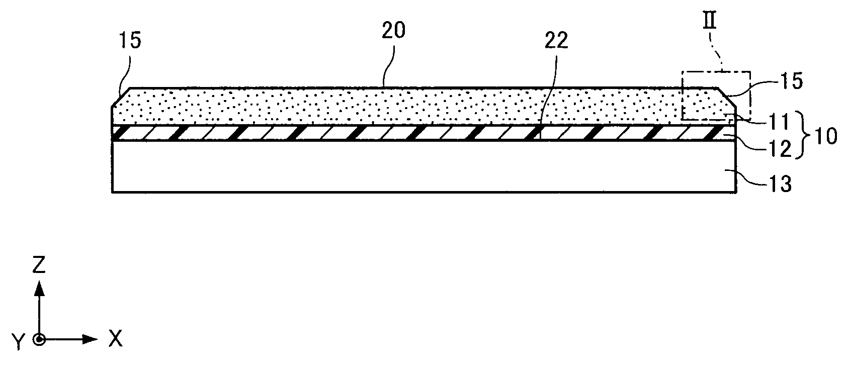
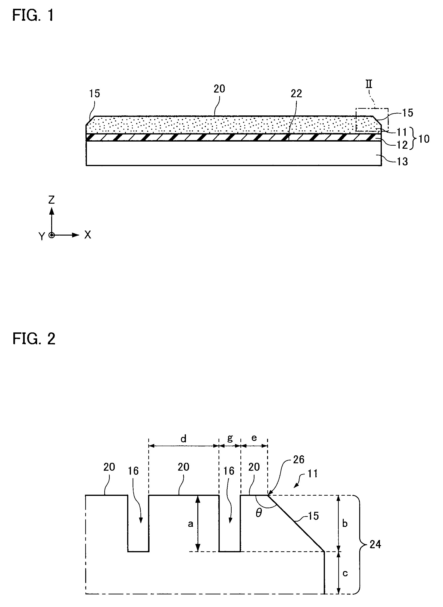
[0119]A chemical mechanical polishing pad was obtained in the same manner as in the production method described in “2.3. Production of chemical mechanical polishing pad (Example 15)”, except that the slope surface was not formed.
2.5 Chemical Mechanical Polishing
[0120]The chemical mechanical polishing pad produced in each of the sections 2.1. to 2.4. was placed on a platen of a chemical mechanical polishing apparatus (“Reflexion-LK” manufactured by Applied Materials), and a P-TEOS blanket wafer was subjected to chemical mechanical polishing. Chemical mechanical polishing was conducted until the edge of the pad was removed from the platen. The time from the start of chemical mechanical polishing to removal of the edge of the pad was measured. The chemical mechanical polishing conditions were as follows.
Chemical Mechanical Polishing Aqueous Dispersion: Silica Abrasive Grain-Containing Slurry (“CMS-1101 ” Manufa...
PUM
 Abstract
Description
Claims
Application Information
 - R&D
- Intellectual Property
- Life Sciences
- Materials
- Tech Scout
- Unparalleled Data Quality
- Higher Quality Content
- 60% Fewer Hallucinations
Browse by: Latest US Patents, China's latest patents, Technical Efficacy Thesaurus, Application Domain, Technology Topic, Popular Technical Reports.
© 2025 PatSnap. All rights reserved.Legal|Privacy policy|Modern Slavery Act Transparency Statement|Sitemap|About US| Contact US: help@patsnap.com


