
Shaft seal apparatus

a shaft seal and seal technology, applied in the direction of engine seals, mechanical devices, engine components, etc., can solve the problems of shaft seal apparatus b>100/b>, inconvenient sealing against high-temperature or high-pressure fluid, and inability to ascertain the accurate retaining of the first sealing portion, etc., to achieve the effect of simple assembly and convenient assembly

Inactive Publication Date: 2009-08-20
EAGLE INDS
View PDF21 Cites 6 Cited by
  • Summary
  • Abstract
  • Description
  • Claims
  • Application Information

AI Technical Summary

Benefits of technology

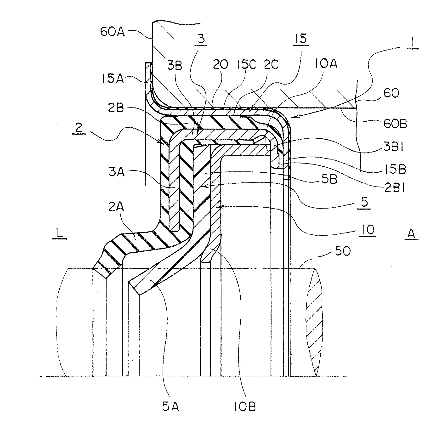
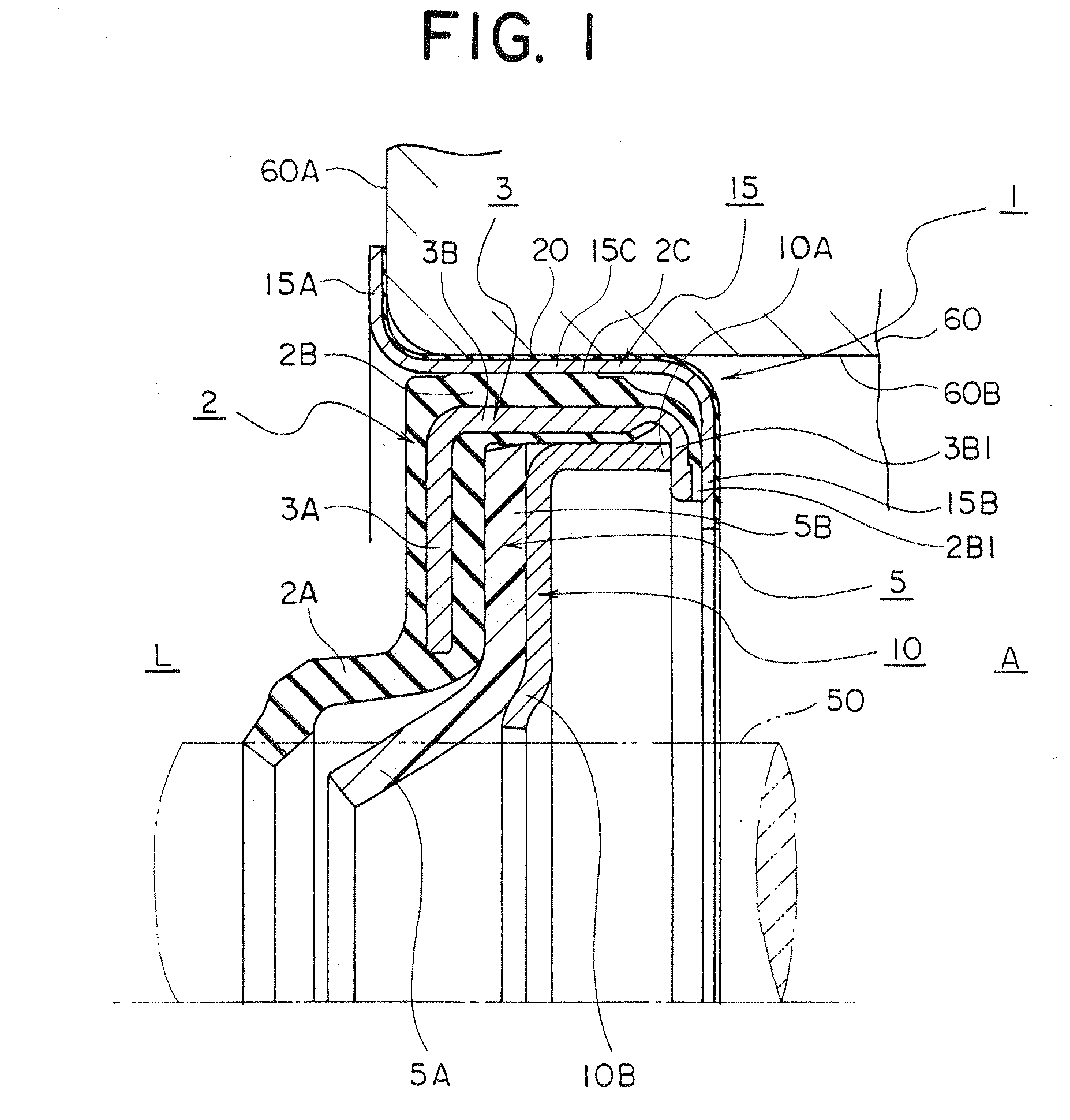
[0018]According to the shaft seal apparatus related to the present invention, the stopper ring which retains the first sealing portion and the second sealing portion against the seal housing disposes a first stopper portion which engages against the end face of the seal housing. Therefore, when the shaft seal apparatus is secured in a specific position of the bore surface of the seal housing, no step shoulder portion needs to be disposed therein for axial positioning. This permits to install into a seal housing comprising a bore surface which a step shoulder portion for positioning is hard to form. At the same time, since the stopper ring having a second stopper portion therein provides a support in conjunction with the reinforcement ring against the first sealing portion and the second sealing portion, the assembly structure becomes simple and the assembling becomes easy.
[0019]Also a seal made of a rubber elastic material in which the thickness of the seal is thinner than that of the reinforcement ring or engagement ring is applied to the fit surface of the seal housing of the engagement ring. Therefore, due to such a thin seal, not only it achieves an easy installation / de-installation of the shaft seal apparatus against the bore surface of the seal housing when replacing, but also provides an effective seal between the seal housing and the engagement ring for a long period. Further, due to the thin wall of the seal, an elastic deformation is small and enables a concentric fitting of the shaft seal apparatus against the rotary shaft. Also since the thin wall nature of the seal prevents the shaft seal apparatus from sticking to the bore surface of the seal housing 60 even after a long period of use, it is easy to remove from the bore surface of the seal housing 60 for replacement.

Problems solved by technology

In particular, the flange portion 110F is prone to the deformation because it contacts with housing 160 which easily heats up and the high-temperature pressurized fluid, thus unable to ascertain the accurate retaining of the first sealing portion 110.
Consequently, a shaft seal apparatus 100 thus configured is not suitable for providing a seal against high-temperature or high-pressure fluid.
Thus, it will be difficult to improve the sealing ability of the shaft seal apparatus 100.
Therefore, the sealing apparatus 200 is not suitable for mass-production.
If rust is formed on the fit surface of the metal ring 210, a strong bonding caused by the rust makes even more difficult to remove from the housing 260.

Method used


Image

  • Shaft seal apparatus
  • Shaft seal apparatus
  • Shaft seal apparatus

Examples


embodiment 1

[0056]First, the embodiment 1 of the shaft seal apparatus 1 according to the present invention is explained. FIG. 1 is a half cross-sectional view of the shaft sealing apparatus 1. Also, FIG. 2 is a half cross-sectional view of the shaft sealing apparatus 1 in FIG. 1 contained in a rotary shaft 50. Further explanations refer to FIG. 1 and FIG. 2. The rotary shaft 50 is installed in a bore surface 60B (hereinafter referred to as a bore) disposed in the housing 60. The shaft seal apparatus 1 provides a seal against pressurized fluid which is contained in machine interior L between the bore 60B and the rotary shaft 50. This pressurized fluid, for instance, is cooling water accompanied with temperature and pressure. More specifically, it provides a seal against cooling water for cooling a radiator or the like.

[0057]A first sealing portion 2 is comprised of a fit mount portion 2B of cylindrical tube design, a first sealing lip 2A extending from one end of the fitting portion 2B in radial...

embodiment 2

[0064]Described next is a shaft sealing apparatus 1 as an embodiment 2 according to the present invention. FIG. 3 shows a half cross-sectional view of a shaft sealing apparatus 1 according to the embodiment 2. The case in FIG. 3 also does not dispose a step shoulder portion in the bore 60B of the seal housing 60 for the axial positioning and fixation of the shaft sealing apparatus 1. What makes it different from FIG. 1 is that the joint portion 2B1 and 3B1 of the first sealing portion 2 are disposed in the first engagement portion 15A side in contrast to the joint portion 2B1 and 3B1 of the first sealing portion 2 appeared in FIG. 1. And the cylindrical portion 3B of the reinforcement ring 3 to the second joint portion 3B is formed in a flange-shape in the same direction as the first engagement portion 15A. The joint portions 2B1 and 3B1 of the first sealing portion 2 are constituted by the second joint portion 3B1 of the reinforcement ring 3 and the first joint portion 2B1 which ex...

embodiment 3

[0067]Next described is a shaft seal apparatus 1 of the embodiment 3 according to the present invention. FIG. 4 shows a half cross-sectional view of a shaft sealing apparatus 1 related to the embodiment 3. The case in FIG. 4 also does not dispose a step shoulder portion in the bore 60B of the seal housing 60 for the positioning and fixation of the shaft sealing apparatus 1. What makes it different from FIG. 1 is that it represents a modification example in which the engagement ring (also referred to as a engagement diaphragm) 15 and the reinforcement ring 3 are arranged integrally. This reinforcement ring 3 has almost an identical form with the reinforcement ring 3 shown in FIG. 1. Furthermore, the engagement ring 15 is joined with the reinforcement ring 3 as shown in FIG. 4, and the cylindrical portion 3B of the reinforcement ring 3 is used as the part corresponding to the fitting portion 15C in FIG. 1. That is, the engagement ring 15 has a first engagement portion 15A therein for ...


PUM


Abstract

The shaft seal apparatus is comprised of a first sealing portion, a second sealing portion, a first backup diaphragm and an engagement ring, wherein the first sealing portion has a fit mount portion, a first sealing lip and a reinforcement ring, in which the fit mount portion is retained sealingly in the seal housing side, in which an inner circumferential surface of the first sealing lip sealingly fits against the outer circumferential surface of the shaft for providing a seal against the pressurized fluid, in which the reinforcement ring has a reinforcement portion, a cylindrical portion and a joint portion, the reinforcement portion provides a reinforcement against the fit mount portion side of the first sealing lip, the cylindrical portion is integrally joined with the fit mount portion, the joint portion is disposed in the other end of the cylindrical portion, wherein the second sealing portion has a support portion and a second sealing lip, in which the second sealing portion is made of a resin material, the support portion is in tight contact against the first sealing portion by the opposite side relative to the pressurized fluid, the support portion is arranged in parallel to the first sealing portion, wherein the first backup diaphragm is supported by the reinforcement ring or an engagement ring which retains the support portion of the second sealing portion, wherein the engagement ring has a fitting portion, a first engagement portion and a second engagement portion in which the fitting portion fits in the bore surface of the seal housing, the first engagement portion engages against the end face of the seal housing, the second engagement portion allows the first engagement portion to support the reinforcement ring, wherein a seal is disposed between the contact surfaces of the engagement ring and the bore surface and the radial thickness of the seal is arranged smaller than the reinforcement ring or the engagement ring.

Description

TECHNICAL FIELD[0001]The present invention relates to a shaft seal apparatus which provides a tight seal against a pressurized fluid in the clearance defined between a rotary shaft which is inserted in a bore surface of a housing and the bore surface. More particularly, this invention relates to a shaft seal apparatus improved a high pressure resistance ability against pressurized fluid and an easy installation by arranging a sealing portion made of a rubber elastic material which is in parallel to another sealing portion made of a resin material.BACKGROUND ART[0002]As a related art relative to the shaft seal apparatus of the present invention, there is a similar shaft seal apparatus disclosed in the patent reference 1 which is described in below. This shaft seal apparatus provides a seal against the pressurized fluid by being installed in the bearing mount bore for a rotary shaft penetrating through the wall of a pump housing. This pressurized fluid, for example, is cooling water f...

Claims


Application Information

Patent Timeline
Patent Type & Authority Applications(United States)
IPC IPC(8): F16J15/32
CPCF16J15/3228F16J15/12F16J15/32
Inventor SANADA, MASAMITSU
Owner EAGLE INDS
Learn More