
Infra-red temperature sensor

a temperature sensor and infrared technology, applied in the field of temperature sensors, can solve the problems of inability to operate the detector, difficulty in combining the limited choice of window materials with the needed robustness against fouling and chemical attack, and achieve the effect of fast response time and cost-effectiveness

Inactive Publication Date: 2009-08-20
GENERAL ELECTRIC CO
View PDF5 Cites 25 Cited by
  • Summary
  • Abstract
  • Description
  • Claims
  • Application Information

AI Technical Summary

Benefits of technology

[0004]An improved infra-red temperature sensor according to this invention is robust against harsh and aggressive environments, has a fast response time, is cost effective for volume applications such as exhaust gas monitoring.
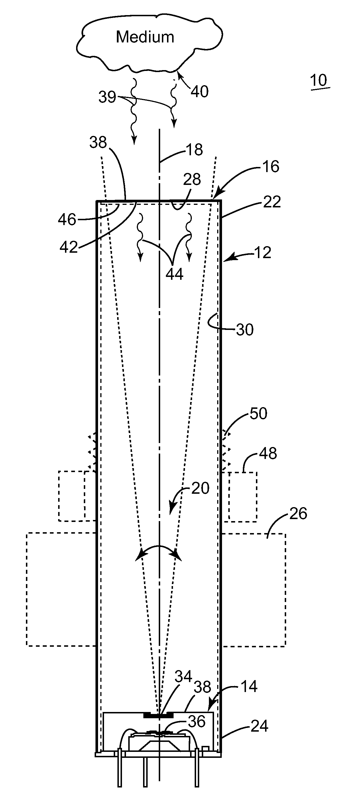
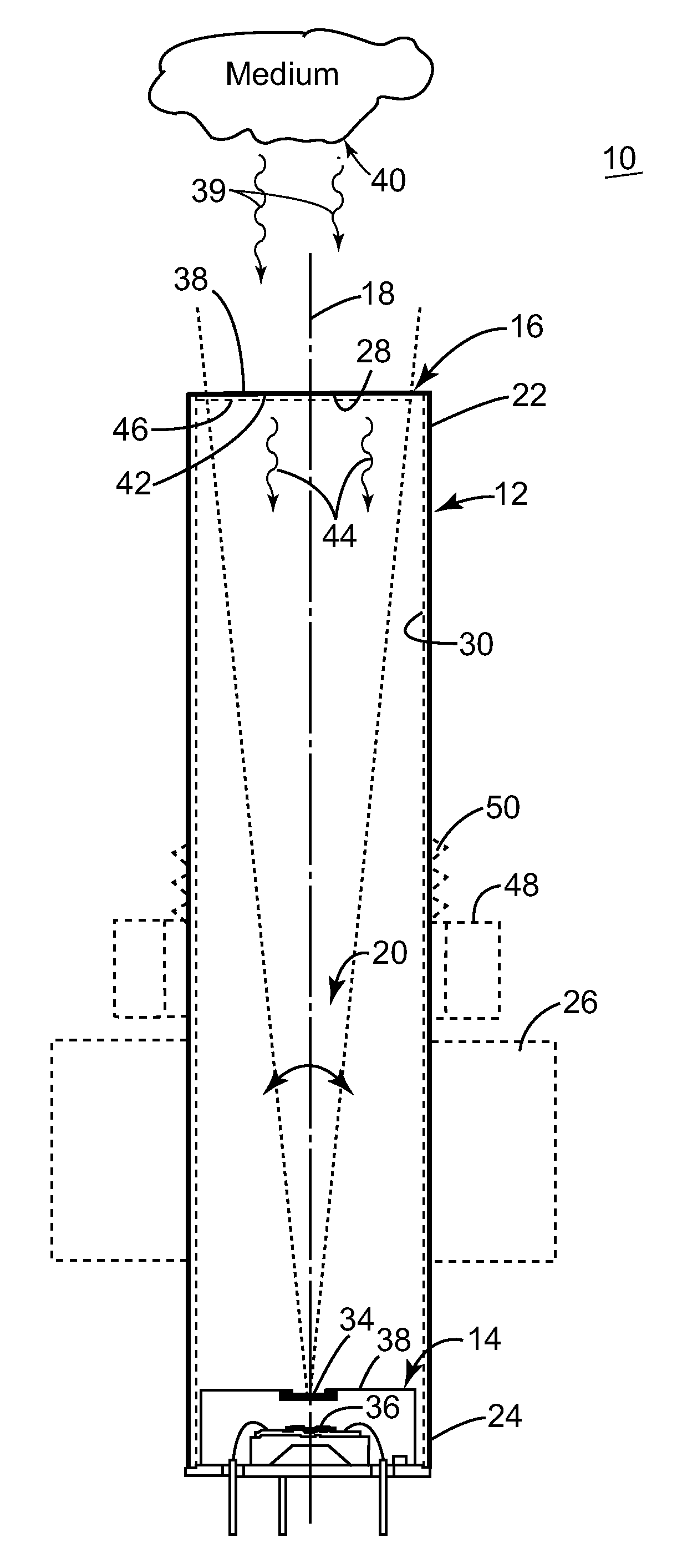
[0005]An improved infra-red temperature sensor which can operate in harsh environments, yet have fast response time can be achieved with a diaphragm that closes the housing and is spaced along an axis from and in the field of view of a thermal infra-red sensor element for absorbing on its outer surface heat from the medium and emitting radiation from its inner surface to the thermal sensor element representative of the temperature of the medium.

Problems solved by technology

However, as with any optical sensor, the detector cannot operate where there is a chance that the window material may get obscured or chemically attacked by contaminants in a harsh environment such as a combustion exhaust stream where temperatures can reach 1000° Celsius and include such harsh materials as hydrochloric and sulfuric acids.
There are relatively few good IR window materials suitable for the 1-14 um wavelength band so it is difficult to combine the limited choice of window materials with the needed robustness against fouling and chemical attack.
Although well suited for use in measuring high temperatures at high speed due to the fact that they can be used without being in physical contact with the item to be measured, the dependence on a consistent optical path has prevented IR sensors being used in many harsh or aggressive environments.
Stable operation of these devices at high temperatures can also still give problems.

Method used


Image

  • Infra-red temperature sensor
  • Infra-red temperature sensor

Examples


Embodiment Construction

[0009]Aside from the preferred embodiment or embodiments disclosed below, this invention is capable of other embodiments and of being practiced or being carried out in various ways. Thus, it is to be understood that the invention is not limited in its application to the details of construction and the arrangements of components set forth in the following description or illustrated in the drawings. If only one embodiment is described herein, the claims hereof are not to be limited to that embodiment. Moreover, the claims hereof are not to be read restrictively unless there is clear and convincing evidence manifesting a certain exclusion, restriction, or disclaimer.

[0010]The invention is a device for quickly measuring the temperature of an object especially a gas or liquid stream in a harsh or aggressive environment such as combustion exhaust where the contaminates may include e.g. hydrochloric acid, sulfuric acid, and the temperature may reach a 1,000 degrees Celsius or more. The inv...


PUM


Abstract

An infra-red temperature sensor for sensing the temperature of a medium includes a housing; a thermal infra-red sensor element having a predetermined field of view and disposed in the housing; and a diaphragm closing the housing spaced along an axis from and in the field of view of the thermal sensor element for absorbing on its outer surface heat from the medium and emitting radiation from its inner surface to the thermal sensor element representative of the temperature of the medium.

Description

FIELD OF THE INVENTION[0001]This invention relates to an improved temperature sensor and more particularly to an infra-red sensor suitable for harsh environments.BACKGROUND OF THE INVENTION[0002]Thermopile infra-red sensors typically have response times of the order of a few tens of milli-seconds due to the very small thermal mass of the detector element responding to the incoming thermal radiation. However, as with any optical sensor, the detector cannot operate where there is a chance that the window material may get obscured or chemically attacked by contaminants in a harsh environment such as a combustion exhaust stream where temperatures can reach 1000° Celsius and include such harsh materials as hydrochloric and sulfuric acids. There are relatively few good IR window materials suitable for the 1-14 um wavelength band so it is difficult to combine the limited choice of window materials with the needed robustness against fouling and chemical attack. Although well suited for use ...

Claims


Application Information

Patent Timeline
IPC IPC(8): G01J5/02
CPCG01J5/041G01J5/042G01J5/0887G01J5/08G01J5/0853G01J5/048
Inventor TWINEY, ROBERT CHRISTOPHERKRELLNER, THEODORE J.STRAUB, PETER J.
Owner GENERAL ELECTRIC CO
Learn More