
Illumination device and display device

a display device and light-emitting technology, applied in the direction of optical radiation measurement, instruments, lighting and heating apparatus, etc., can solve the problems of loss of color balance due to the change of light-emitting wavelength, high cost of optical sensor with wavelength detection function, etc., and achieve the effect of appropriately maintaining the color balance of ligh

Inactive Publication Date: 2009-08-20
SONY CORP
View PDF3 Cites 27 Cited by
  • Summary
  • Abstract
  • Description
  • Claims
  • Application Information

AI Technical Summary

Benefits of technology

[0008]Thus, it is desirable to provide a configuration which can appropriately correct deviation in the color balance due to change of the light-emitting wavelength of the light emitting element even when the expensive optical sensor having the wavelength detection function is not used.
[0028]In the first illumination device and the first display device according to the embodiment of the invention, for example, even when the junction temperature of the light emitting element is changed according to change of peripheral temperature, light emitting luminance and the like of the light emitting element, drive current to the light emitting element is controlled so that the light amount (light emitting amount) of the light emitting element corresponds to the light amount target value set in accordance with the junction temperature, therefore, the light amount of the light emitting element can be appropriately maintained.
[0030]In the third illumination device and the third display device according to the embodiments of the invention, it is possible to appropriately set the light amount target value (setting change when the light amount target value has been already set) according to changes of the junction temperature of the light emitting element when the light emitting element is driven in the optimum drive condition and when the light emitting element is drive in other drive conditions.
[0031]In the forth illumination device and the fourth display device according to the embodiments of the invention, it is possible to appropriately maintain color balance of light obtained by adding (combining) lights generated by the light emitting elements of respective colors by setting the light amount target value in accordance with junction temperatures of respective light emitting elements. Therefore, even when a light emitting wavelength of the light emitting element changes with change of, for example, the peripheral temperature or the light emitting luminance of the light emitting element, deviation (particularly, losing of white balance) in the color balance caused by the change of the light emitting wavelength of the light emitting element can be appropriately corrected without an expensive optical sensor having a wavelength detection function).
[0032]In the fifth illumination device and the fifth display device according to the embodiments of the invention, it is possible to appropriately set light amount values to be applied to respective light emitting elements so that the color balance of light obtained by adding (combining) lights generated by the light emitting elements of respective colors is fixed.
[0033]In the sixth illumination device and the sixth display device according to the embodiments of the invention, it is possible to detect the junction temperature of the light emitting elements in real time.

Problems solved by technology

However, the optical sensor having the wavelength detection function is generally expensive, and is not adequate for miniaturization.
Therefore, for example, in the case that the light-emitting efficiency of the LED is changed due to secular change, the color balance is lost due to change of the light-emitting wavelength even when drive current is adjusted for compensating the change (lowering) of the amount of light.
Also, in the case that the light-emitting luminance of the LED is changed by a video signal and the like, the color balance is lost because the light-emitting wavelength is changed due to change of the junction temperature of the LED even when the peripheral temperature of the LED is fixed.

Method used


Image

  • Illumination device and display device
  • Illumination device and display device
  • Illumination device and display device

Examples


Embodiment Construction

[0037]Hereinafter, specific embodiments of the invention will be explained in detail with reference to the drawings. Note that the technical range of the invention is not limited to the embodiments described below and includes forms to which various modifications and improvement are added within a scope in which specific advantages obtained by constituent features of the invention or combination thereof can be derived.

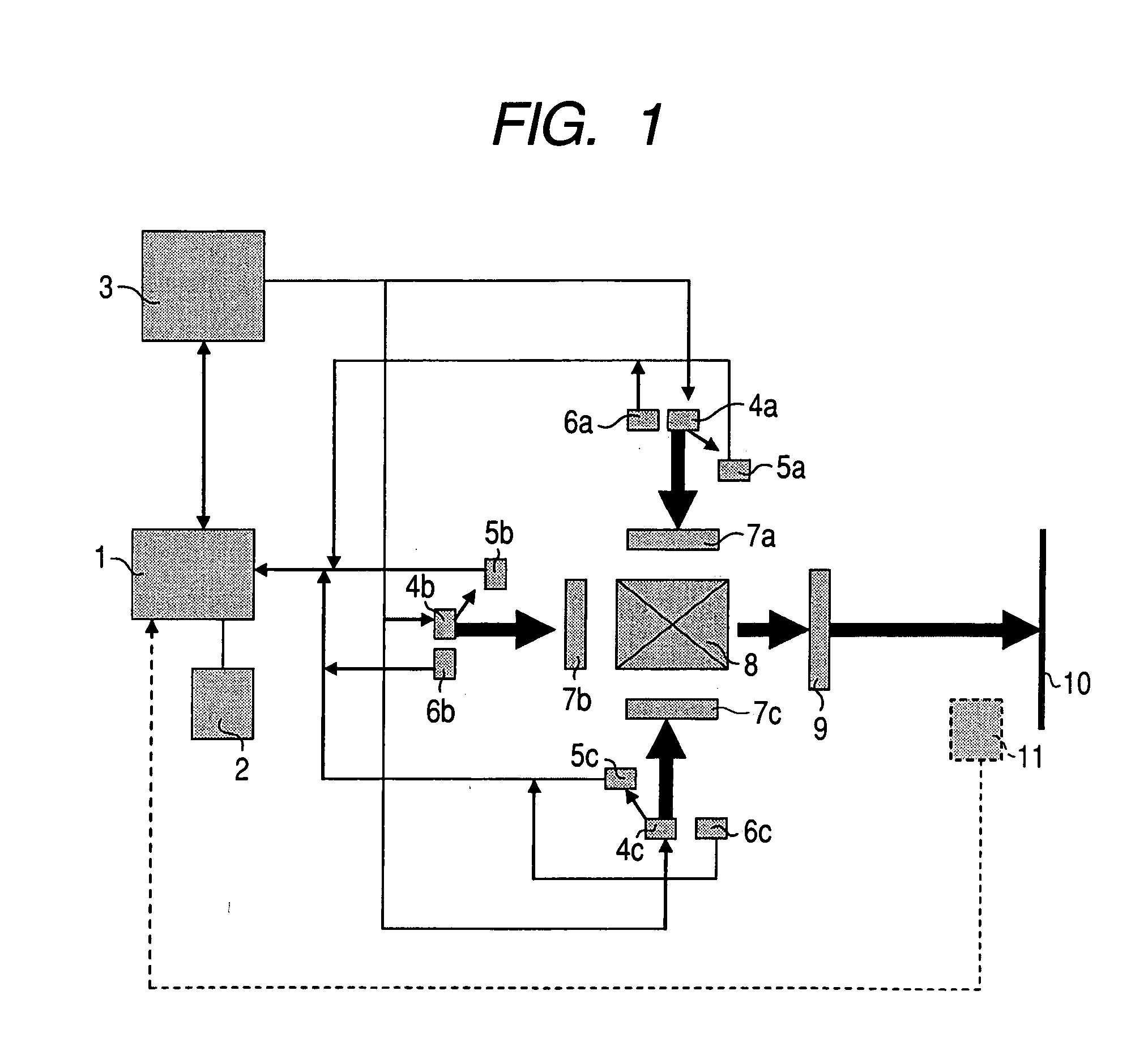
[0038]FIG. 1 is a schematic diagram showing a configuration example of a display device according to an embodiment of the invention. The shown display device is a projection-type display device, including a computing unit 1, a storage unit 2, a LED drive unit 3, LEDs 4, optical sensors 5, temperature sensors 6, light modulation devices 7, a light combining device 8, and a projection lens 9. The LEDs 4, the optical sensors 5, the temperature sensors 6 and the light modulation devices 7 are separately provided with respect to respective color components (light emitting c...


PUM


Abstract

An illumination device includes: a light emitting element to be a light source; a light amount detecting means for detecting the amount of light emitted by the light emitting element; a light emitting element drive means for controlling drive current supplied to the light emitting element so that the difference between the light mount detected by the light amount detecting means and a light amount target value becomes small; a junction temperature detecting means for calculating junction temperature of the light emitting element; and a setting means for setting the light amount target value in accordance with the junction temperature detected by the junction temperature detecting means.

Description

CROSS REFERENCE TO RELATED APPLICATIONS[0001]The present invention contains subject matter related to Japanese Patent Application JP 2008-032743 filed in the Japanese Patent Office on Feb. 14, 2008, the entire contents of which being incorporated herein by reference.BACKGROUND OF THE INVENTION[0002]1. Field of the Invention[0003]The invention relates to an illumination device and a display device including the same.[0004]2. Description of the Related Art[0005]In recent years, an illumination device using a light-emitting diode (hereinafter, “LED”) as a light source is utilized in various fields. For example, in projective-type display devices, there exist a device including an illumination device having three types of LEDs as a light source, which generate light of wavelengths corresponding respective color components of red, green and blue which are three primary colors of light. The display device of this type adds lights generated by three types of LEDs to obtain white light. At ...

Claims


Application Information

Patent Timeline
Patent Type & Authority Applications(United States)
IPC IPC(8): G01J1/32
CPCG01J1/32H05B33/0869H04N9/3194H04N9/3182H05B33/0872H05B45/22H05B45/28
Inventor KAWASHIMA, TOSHIYUKIOGAWA, SHINJIKODAMA, TAKESHI
Owner SONY CORP
Learn More