
Electronic devices that pan/zoom displayed sub-area within video frames in response to movement therein

a technology of electronic devices and video frames, applied in the field of electronic devices, can solve the problems of unacceptably difficult viewing of movie features, small display size, and difficulty in commercial success of such portable electronic devices, and achieve the effect of enlargement and size reduction

Active Publication Date: 2009-08-13
SONY CORP
View PDF10 Cites 49 Cited by
  • Summary
  • Abstract
  • Description
  • Claims
  • Application Information

AI Technical Summary

Benefits of technology

The patent describes an electronic device that can identify movement in video frames and pan or zoom in to display a smaller area of the video frames that includes the movement. This allows for easier viewing of the movement and can be done based on the direction and speed of the movement. The device can also detect and correlate the movement with the voice characteristics of the person or the content of the video frames. The technical effect of this invention is to provide a more immersive viewing experience for users of the electronic device.

Problems solved by technology

Commercial success of such portable electronic devices may be hindered by their relatively small display size.
Unfortunately, when movies are played on the relatively small displays of portable electronic devices, some features within the movies may be unacceptably difficult to view, which may lead to decreased acceptability of such devices.
Accordingly, providing effective movie viewing or other video viewing through electronic devices, such as portable electronic devices, continues to be a challenge.

Method used

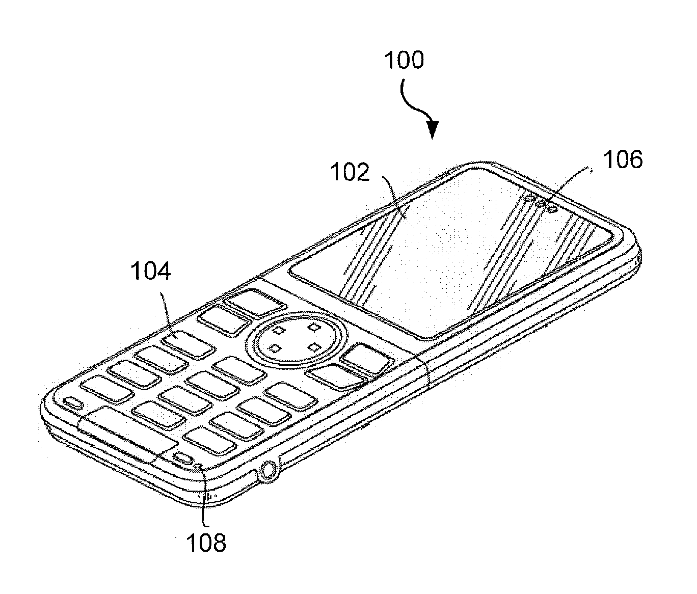
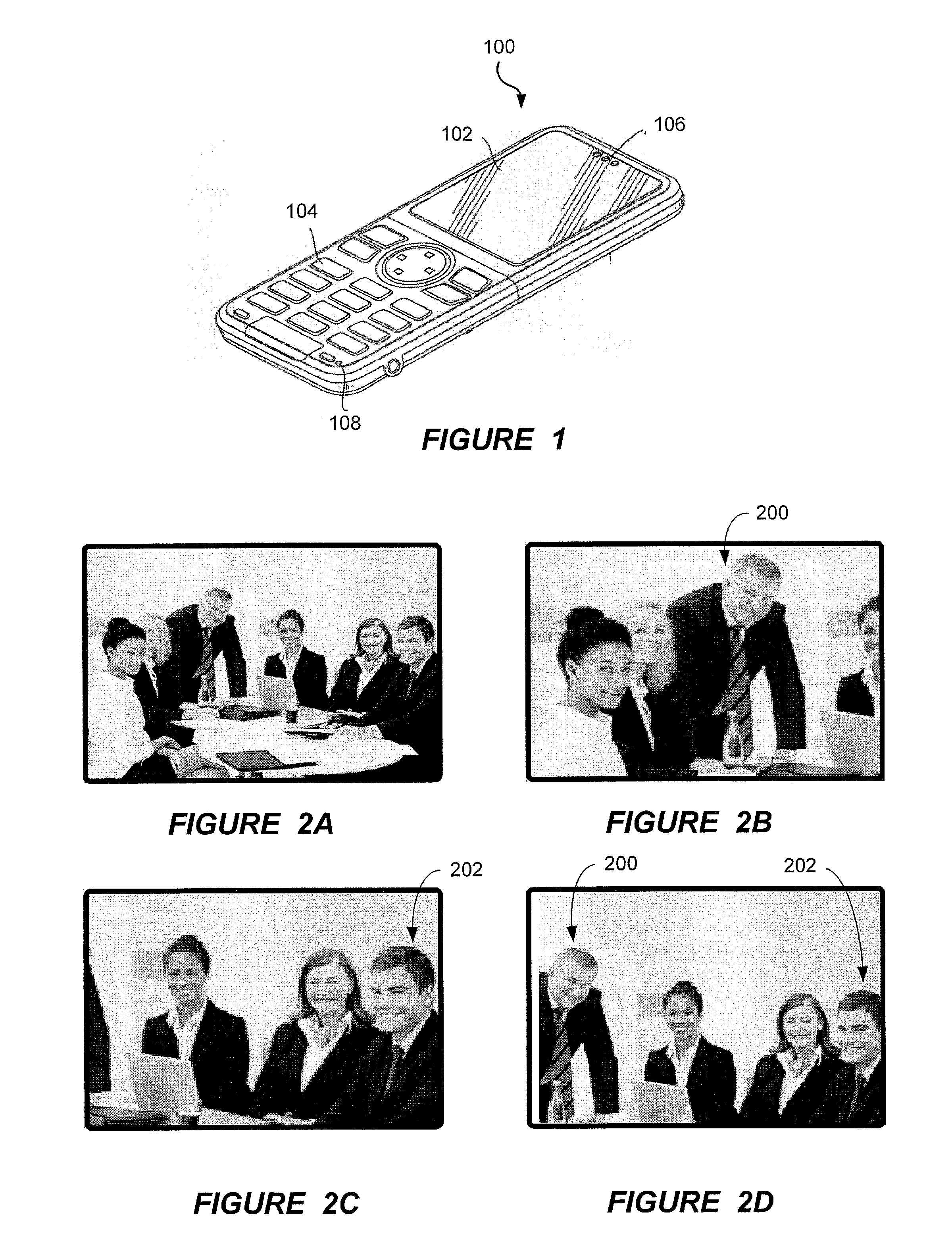
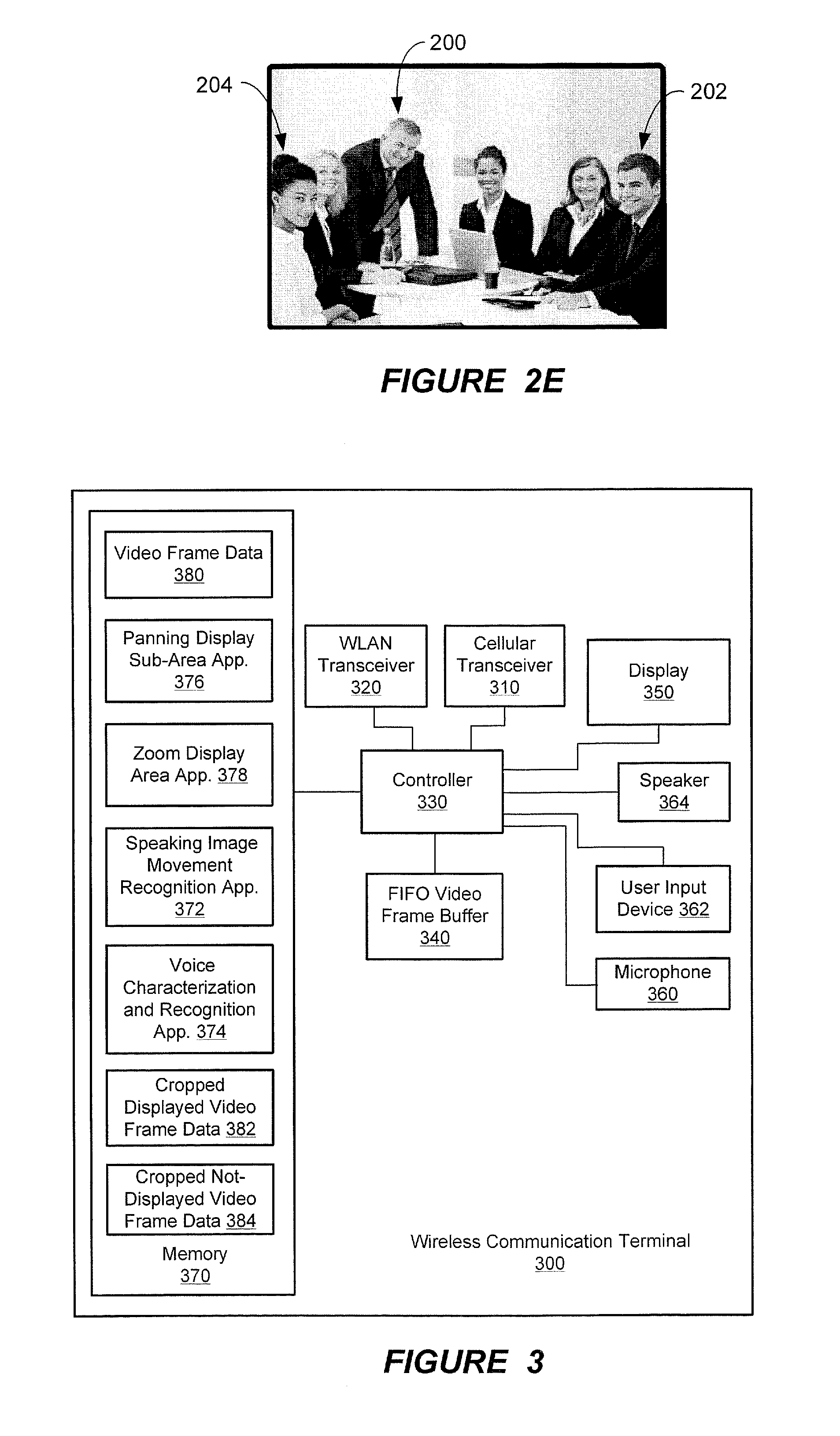

Image

  • Electronic devices that pan/zoom displayed sub-area within video frames in response to movement therein
  • Electronic devices that pan/zoom displayed sub-area within video frames in response to movement therein
  • Electronic devices that pan/zoom displayed sub-area within video frames in response to movement therein

Examples


Embodiment Construction

[0036]The present invention will be described more fully hereinafter with reference to the accompanying figures, in which embodiments of the invention are shown. This invention may, however, be embodied in many alternate forms and should not be construed as limited to the embodiments set forth herein.

[0037]Accordingly, while the invention is susceptible to various modifications and alternative forms, specific embodiments thereof are shown by way of example in the drawings and will herein be described in detail. It should be understood, however, that there is no intent to limit the invention to the particular forms disclosed, but on the contrary, the invention is to cover all modifications, equivalents, and alternatives falling within the spirit and scope of the invention as defined by the claims. Like numbers refer to like elements throughout the description of the figures.

[0038]The terminology used herein is for the purpose of describing particular embodiments only and is not inten...


PUM


Abstract

An electronic device can include a display and a controller. The controller identifies a location within a displayable area of video frames which has movement, and controls panning / zooming of a sub-area within the video frames that is displayed on the display in response to the identified location of the movement. Some configurations of the controller detect movement of a person's mouth within the video frames while the person is speaking, identifies the associated location of the person speaking, identifies characteristics of voice in the video frames that is concurrently occurring with the detected movement of the person's mouth, and correlates the identified voice characteristics with the identified location of the person speaking. The controller then detects subsequent occurrence of voice in the video frames having the identified voice characteristics of the person and, responsive thereto, pans a sub-area within the video frames displayed on the display toward the identified location of the person and / or zooms-in to increase size of the person speaking by decreasing size of a sub-area within the video frames at the location of the speaker that is fit to the display.

Description

FIELD OF THE INVENTION[0001]The present invention generally relates to the field of electronic devices such as wireless communication terminals, and more particularly to apparatus and methods that control the display of video on electronic devices.BACKGROUND OF THE INVENTION[0002]Electronic devices, such as wireless communication terminals and other portable electronic devices, have evolved to include increasingly more functionality. For example, some wireless communication terminals have sufficient capacity to store and then play-back full-length movies. Additionally or alternatively, some wireless communication terminals have sufficient communication bandwidth to allow users to download and view streaming video, such as a movie and / or a video-conference, across a wireless communication network.[0003]Commercial success of such portable electronic devices may be hindered by their relatively small display size. Movies are generally composed with an expectation that they will be displ...

Claims


Application Information

Patent Timeline
Patent Type & Authority Applications(United States)
IPC IPC(8): G09G5/00G06V10/25
CPCG06K9/3233G06K9/00228G06V40/161G06V10/25
Inventor THORN, KARL OLA
Owner SONY CORP
Learn More