
Image Forming System, Image Forming Apparatus, User Interface Device, Extended User Interface Compatibility Confirming Method, Document Scanning Method and Setting Value Managing Method

Active Publication Date: 2009-08-06
KYOCERA DOCUMENT SOLUTIONS INC
View PDF11 Cites 24 Cited by
  • Summary
  • Abstract
  • Description
  • Claims
  • Application Information

AI Technical Summary

Benefits of technology

[0015]An objective of this invention is to provide an extended user interface compatibility confirming method, and a user interface device and an image forming system thereof, capable of automatically determining whether the image forming apparatus is compatible with the user interface device in a short time.
[0099]By the sixteenth aspect, the image forming apparatus prevents scan operations that a user does not intend.

Problems solved by technology

If the extended user interface device sends the web service request in an incompatible format, then only after a predetermined time has elapsed without any responses, the extended user interface device can find the incompatibility or that the image forming apparatus is not capable of receiving a web service request.
As a result, it takes a long time to automatically determine whether the image forming apparatus is compatible with the extended user interface device, and it also takes a long time for the extended user interface device to become in a ready state after the extended user interface device is started.
Consequently, even if an image forming apparatus has both of the scan modes, the image forming apparatus can not use “continuous scan mode” that is incompatible with the user interface device.

Method used


Image

  • Image Forming System, Image Forming Apparatus, User Interface Device, Extended User Interface Compatibility Confirming Method, Document Scanning Method and Setting Value Managing Method
  • Image Forming System, Image Forming Apparatus, User Interface Device, Extended User Interface Compatibility Confirming Method, Document Scanning Method and Setting Value Managing Method
  • Image Forming System, Image Forming Apparatus, User Interface Device, Extended User Interface Compatibility Confirming Method, Document Scanning Method and Setting Value Managing Method

Examples


embodiment 1

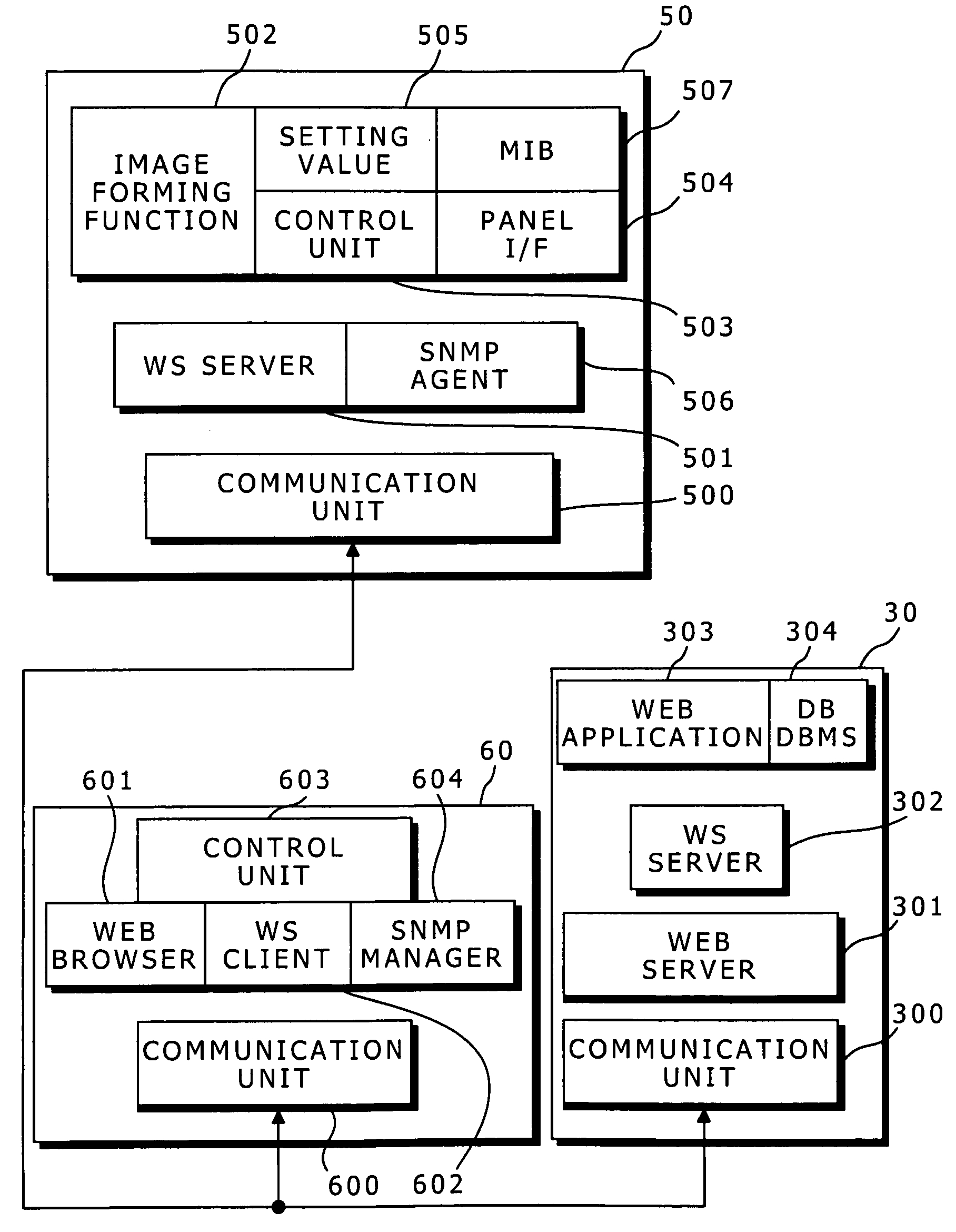
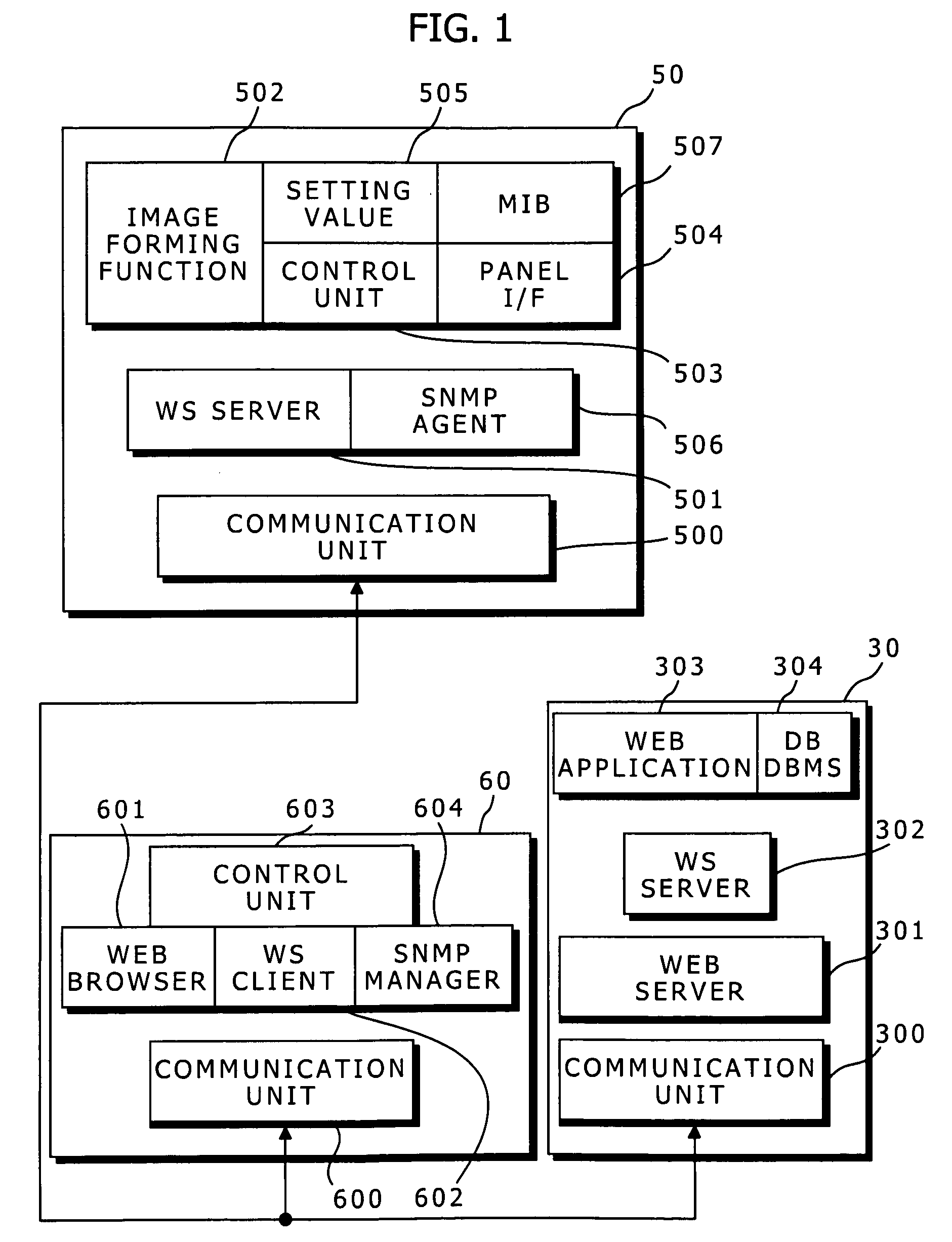
[0130]FIG. 5 shows a schematic diagram that indicates an image forming system according to Embodiment 1 of this invention.

[0131]In the system, image forming apparatuses 10 and 20, and a server 30 are connected to a LAN 40. The type of the image forming apparatus 10 and the type of the image forming apparatus 20 are different from each other. For simplicity, the system has only two image forming apparatuses, but the system may have three or more image forming apparatuses.

[0132]The server 30 provides a common service to image forming apparatuses of which machine types are not identical, and manages screen transitions of user interface screens on the image forming apparatuses to uniform the user interface screens, and executes processes such as a process to reduce a scanned document image to generate a preview image according to a request. To cooperate with the server 30, in the apparatus 10, an extended user interface device 60 is attached to an image forming apparatus 50 (i.e. an ima...

embodiment 2

[0186]A basic configuration of an image forming system according to Embodiment 2 of this invention is the same as that according to Embodiment 1 (FIG. 5).

[0187]Hereinafter, a relationship between the apparatus 10 and the server 30 in Embodiment 2 will be explained, and a relationship between the apparatus 20 and the server 30 is the same as that between the apparatus 10 and the server 30.

[0188]A hardware configuration of the image forming system according to Embodiment 2 is the same as that according to Embodiment 1 (FIG. 6).

[0189]In Embodiment 2, in the PROM 53 of the image forming apparatus 50, an operating system (OS), drivers, programs to be executed in an upper layer of the OS, and setting values have been stored. The programs are executed to embody an image forming function part, a web service server (a WS server), a processing part (i.e. a panel interface) for the operation panel, and a control unit for these processing parts.

[0190]Image forming functions of the image forming...

embodiment 3

[0234]A basic configuration of an image forming system according to Embodiment 3 of this invention is the same as that according to Embodiment 1 (FIG. 5).

[0235]Hereinafter, a relationship between the apparatus 10 and the server 30 in Embodiment 3 will be explained, and a relationship between the apparatus 20 and the server 30 is the same as that between the apparatus 10 and the server 30.

[0236]A hardware configuration of the image forming system according to Embodiment 3 is the same as that according to Embodiment 1 (FIG. 6).

[0237]In Embodiment 3, in the PROM 53 of the image forming apparatus 50, an operating system (OS), drivers, programs to be executed in an upper layer of the OS, and setting values have been stored. The programs are executed to embody an image forming function part, a web service server (a WS server), and a setting part. Image forming functions of the image forming function part includes copying, scanning, printing, transmitting and receiving facsimile data, and ...


PUM


Abstract

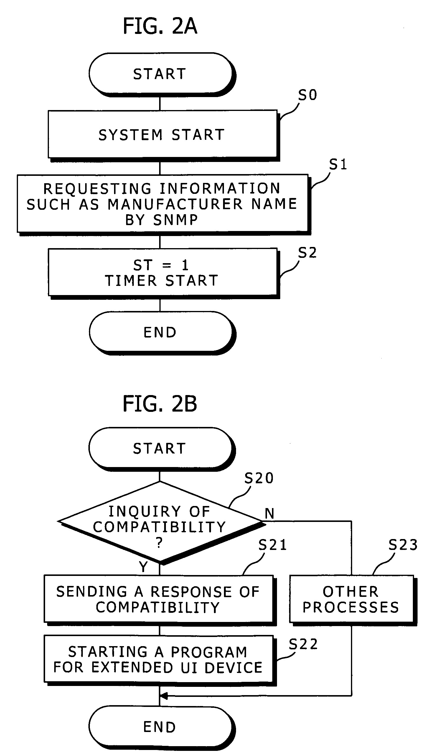
An extended user interface compatibility confirming method has the steps of:(a) connecting an image forming apparatus and an extended user interface device to a network, the extended user interface device having an extended operation panel and sending a web service request from the extended operation panel to the image forming apparatus to perform an image forming function corresponding to the web service request;(b) requesting manufacturer information of the image forming apparatus from the image forming apparatus with SNMP protocol by the extended user interface device, and receiving the manufacturer information from the image forming apparatus by the extended user interface device; and(c) sending a web service request compatible with the manufacturer information to the image forming apparatus by the extended user interface device to inquire whether or not the image forming apparatus is capable of using the extended user interface device.

Description

CROSS-REFERENCE TO RELATED APPLICATIONS[0001]This application relates to and claims priority rights from Japanese Patent Applications:[0002]No. 2008-024764, filed on Feb. 5, 2008,[0003]No. 2008-024762, filed on Feb. 5, 2008,[0004]No. 2008-024760, filed on Feb. 5, 2008,[0005]No. 2008-024763, filed on Feb. 5, 2008, and[0006]No. 2008-074357, filed on Mar. 21, 2008,the entire disclosures of which are hereby incorporated by reference herein.BACKGROUND OF THE INVENTION[0007]1. Field of the Invention[0008]This invention relates to image forming system, image forming apparatus, user interface device, extended user interface compatibility confirming method, document scanning method, and setting value managing method.[0009]2. Description of the Related Art[0010]To uniform user interface screens of a plurality of image forming apparatuses that manufacturers and / or types are different from each other, extended user interface devices are sometimes attached to the image forming apparatuses, respe...

Claims


Application Information

Patent Timeline
IPC IPC(8): G06F15/173G06F3/01G06F3/12H04N1/04
CPCH04L41/0213H04L67/02H04L41/0853H04L41/12H04N1/00129H04N1/00217H04N1/00222H04N1/00244H04N1/00408H04N1/00482H04N1/32789H04N2201/0015H04N2201/0072H04L67/125H04L41/0273
Inventor YASUI, TORUTAKAISHI, HIROYUKI
Owner KYOCERA DOCUMENT SOLUTIONS INC
Learn More