System and Method for Liquid Filtration with Reduced Hold-Up Volume

a liquid filtration and hold-up volume technology, applied in the direction of adhesive processes, membranes, separation processes, etc., can solve the problems of increased pressure drop, excessive internal flow channels of disposable devices, and unnecessary hold-up volum

Inactive Publication Date: 2009-08-06
ENTEGRIS INC
View PDF16 Cites 3 Cited by
  • Summary
  • Abstract
  • Description
  • Claims
  • Application Information

AI Technical Summary

Problems solved by technology

Despite advances in the field, disposable devices typically have excessively large internal flow channels, which are larger than the equivalent inlet and outlet ports and / or tubing and piping leading to and from the device.
These large flow channels result in unnecessary hold-up volume and increases in pressure drop, due to expansions and contractions in the fluid flow path.
Pressure fluctuations caused by the expansions and contractions can cause bubbles in the fluid that is being filtered to come out of solution.
Increased pressure drop is detrimental to fluid processes that are sensitive to outgassing.
The higher pressure required results in more dissolved gas and a greater occurrence of outgassing.
Outgassing relates directly to defects in end use.
Also, a larger amount of hold-up volume causes the filter to take a longer amount of time to prime and flush to background particle levels before use.
Thus, they suffer from similar problems produced by unnecessary hold-up volume.

Method used


Image

  • System and Method for Liquid Filtration with Reduced Hold-Up Volume
  • System and Method for Liquid Filtration with Reduced Hold-Up Volume
  • System and Method for Liquid Filtration with Reduced Hold-Up Volume

Examples


first embodiment

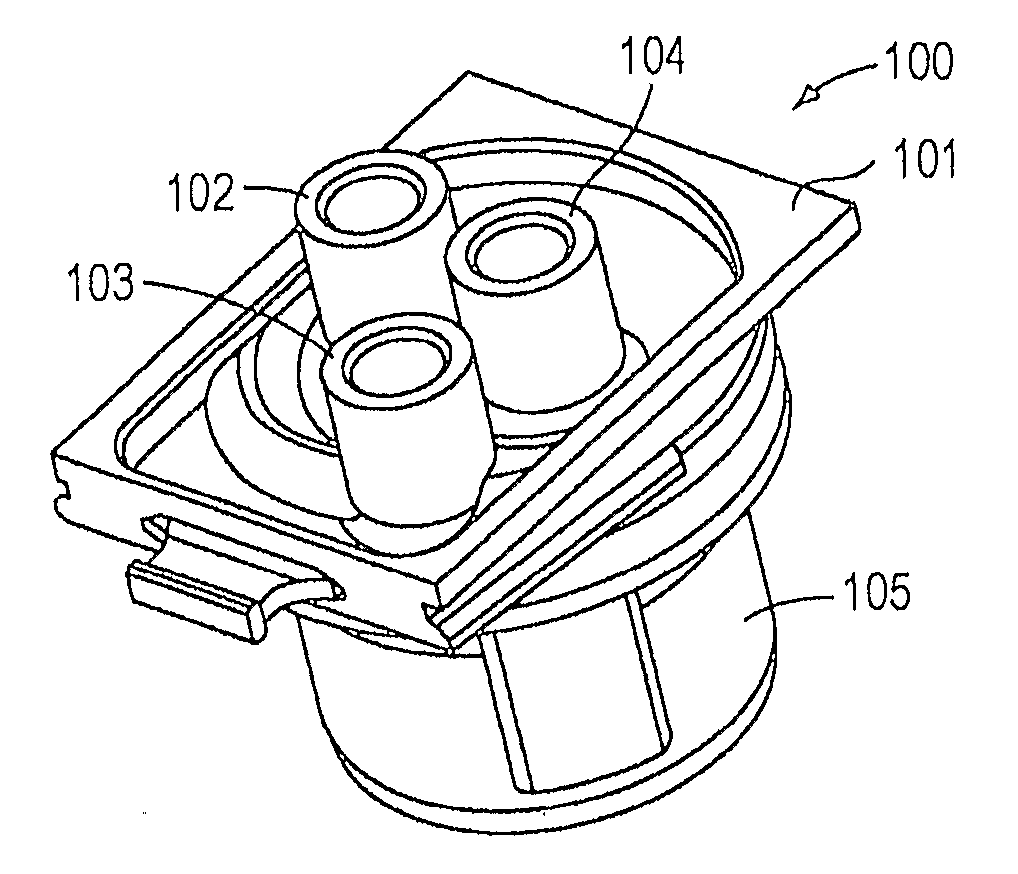
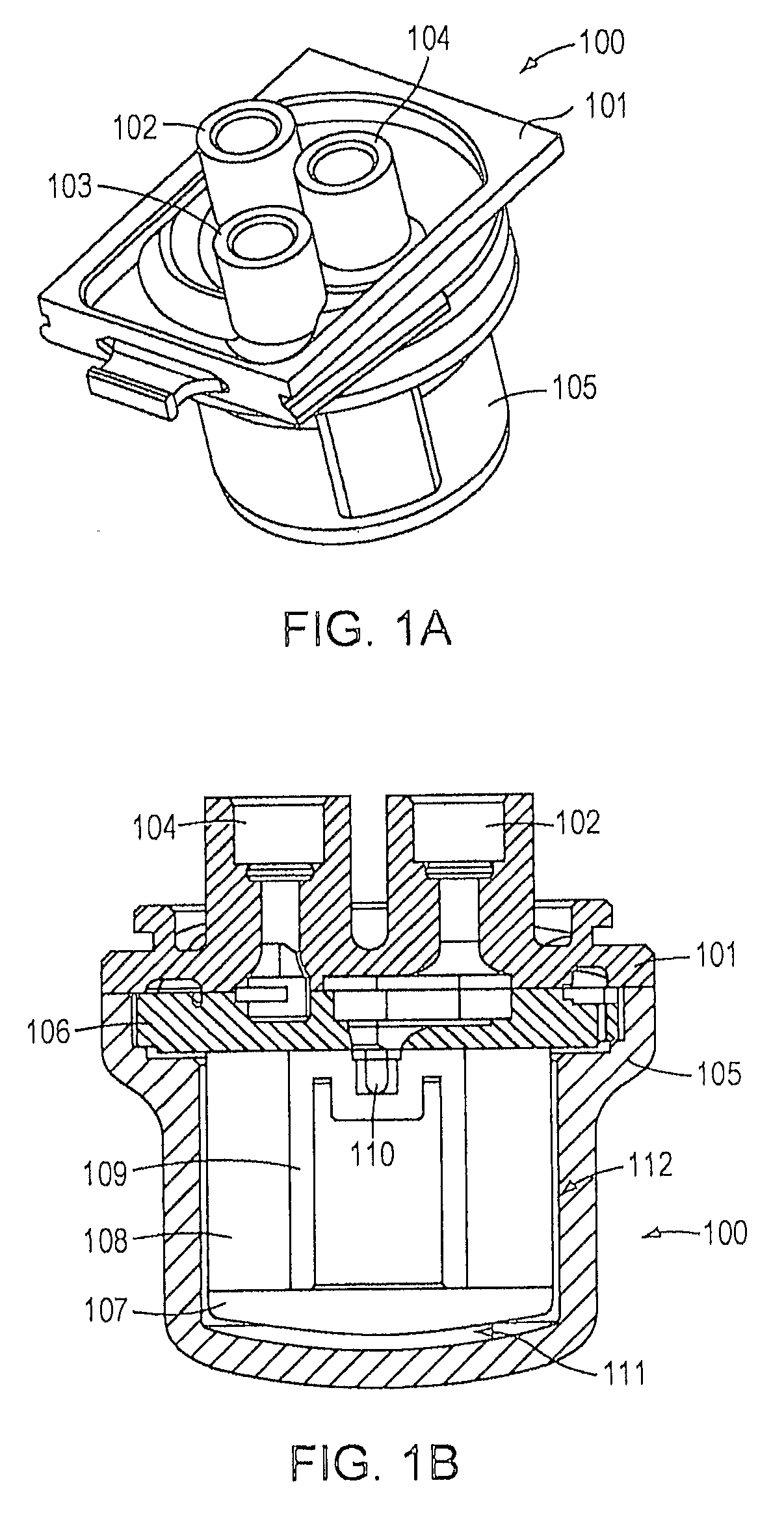
[0024]In accordance with the invention, there is provided a disposable filter device that achieves a significantly reduced hold-up volume and reduced flush-up time by comparison with previous devices, without appreciably increasing the pressure drop across the device. The reduced hold-up volume and reduced flush-up time are achieved by a number of features.

[0025]The filter device does not have a cage or sleeve surrounding the filter, since a cage is not necessary to protect the filter when housed inside a disposable container. As used herein, a disposable filter device is one that can be installed and removed as a unit and can be disposed of after removal. When the filter membrane within the module needs replacement, the entire filter device is removed from the system in which it is used, and disposed of.

[0026]The outer diameter of the filter is a tight fit inside the bowl of the container. By a “tight fit,” it is intended that the fit should be tight enough to support the filter me...

second embodiment

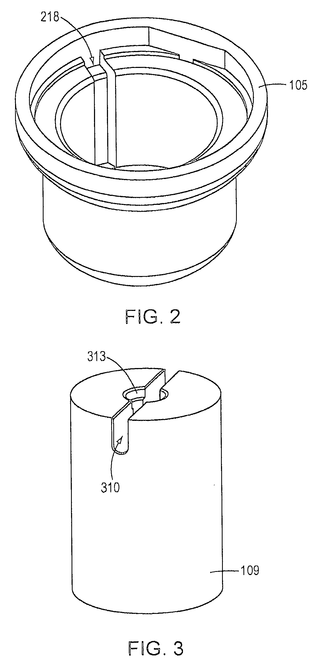
[0043]FIG. 5A shows a unitary bowl, core, and bottom cap for a filter device, according to the invention. In this embodiment, a unitary structure 514 includes a bowl 505, a core region 509, and a bottom cap region 507. The core region 509 includes a cross hole 510 at or near the top surface of the core for assisting with venting during priming, and subsequently conveying fluid to the outlet, in a similar fashion to the cross hole 110 of the embodiment of FIG. 1B. The unitary structure 514 may be molded, for example, of high density polyethylene.

[0044]FIG. 5B shows a cross sectional view of the unitary bowl, core, and bottom cap of the embodiment of FIG. 5A, showing bowl 505, core region 509, bottom cap region 507, and cross hole 510.

[0045]FIG. 6A shows a cross-sectional view of an assembled filter device using a unitary bowl, core, and bottom cap, according to the embodiment of FIGS. 5A and 5B. A head section 601 similar to that of FIGS. 1A and 1B is fitted to the unitary bowl, core...


PUM

PropertyMeasurementUnit
Diameteraaaaaaaaaa
Lengthaaaaaaaaaa
Volumeaaaaaaaaaa

Abstract

In one embodiment according to the invention, there is provided a filter device for liquid filtration, the filter device being in fluid communication with a plurality of liquid pathways, at least one pathway of the plurality of liquid pathways having a smallest equivalent fluid flow diameter of the plurality of liquid pathways. The device comprises a filter membrane (108) and a filter core (109) comprising at least one cross hole (110) in fluid communication with the filter membrane, each cross hole having an equivalent fluid flow, diameter. The sum of the equivalent fluid flow diameters of the at least one cross holes does not exceed the smallest equivalent fluid flow diameter of the plurality of liquid pathways.

Description

RELATED APPLICATION[0001]This application claims the benefit of U.S. Provisional Application No. 60 / 815,375, filed on Jun. 21, 2006, the entire contents of which are incorporated herein by reference.BACKGROUND OF THE INVENTION[0002]Conventional filter devices, used in fields such as the point-of-use filtration of chemicals used in semiconductor manufacturing, are of two types: disposable devices and cartridge filters.[0003]Despite advances in the field, disposable devices typically have excessively large internal flow channels, which are larger than the equivalent inlet and outlet ports and / or tubing and piping leading to and from the device. These large flow channels result in unnecessary hold-up volume and increases in pressure drop, due to expansions and contractions in the fluid flow path. Pressure fluctuations caused by the expansions and contractions can cause bubbles in the fluid that is being filtered to come out of solution. Increased pressure drop is detrimental to fluid p...

Claims


Application Information

Patent Timeline
IPC IPC(8): B01D63/06C09J5/02
CPCB01D63/00B01D63/14B01D2313/44B01D2313/12B01D2313/10B01D29/11B01D29/92B01D29/21
Inventor NORRIS, DOUGLAS A. D.TOWLE, TIMOTHY W.
Owner ENTEGRIS INC
Why Eureka
Try Eureka