
Mufflers with polymeric bodies and process for manufacturing same

a technology of polymeric bodies and mufflers, which is applied in the direction of mechanical equipment, machines/engines, other domestic objects, etc., can solve the problems of polymeric bushings described in u.s. patent no. 6,543,577, and affecting the quality of mufflers

Inactive Publication Date: 2009-08-06
EI DU PONT DE NEMOURS & CO
View PDF9 Cites 34 Cited by
  • Summary
  • Abstract
  • Description
  • Claims
  • Application Information

AI Technical Summary

Benefits of technology

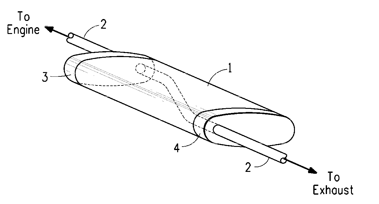
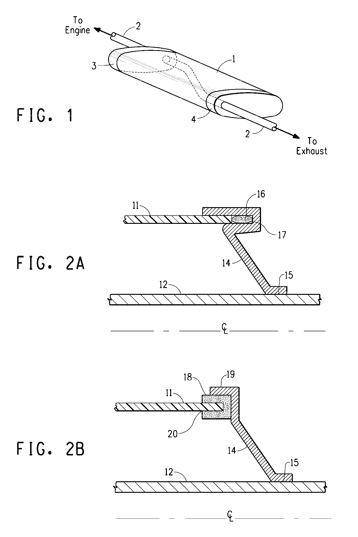
[0005]One aspect of the invention is a muffler system, comprising a metal exhaust pipe attached to and passing through a first body mounting adapter, and attached to and passing through a second body mounting adapter; between said first and second mounting adapter said metal exhaust pipe being encased by a polymeric muffler body attached to the said first and second body mounting adapters to provide a muffler interior, said muffler interior having an air gap, said air gap being a space in between said exhaust pipe and said polymeric muffler body in the vicinity of said first body mounting adapter and / or said second body mounting adapter that is filled with air, and said first body mounting adapter and said second mounting adapter hold said polymeric body a distance from said exhaust pipe so that said polymeric muffler body does not suffer significant thermal damage during operation of said muffler system.

Problems solved by technology

Nevertheless mufflers have tended to be bulky (needed to reduce the noise sufficiently), and heavy because of the high density of metals.
However mounting these mufflers onto an exhaust pipe has proved problematical, since the exhaust pipe may reach very high temporaries (>400° C. in certain designs and / or under certain operating conditions), which has caused the melting and / or degradation of the polymeric muffler and or its mounts.
For instance the polymeric bushings described in U.S. Pat. No. 6,543,577 often degrade because of heating by the exhaust pipe.
However the design of the mounting for these mufflers is cumbersome, involving multiple parts and / or not allowing for easy attachment and / or removal of the muffler body, and requiring the use of insulation.

Method used


Image

  • Mufflers with polymeric bodies and process for manufacturing same
  • Mufflers with polymeric bodies and process for manufacturing same
  • Mufflers with polymeric bodies and process for manufacturing same

Examples


Embodiment Construction

[0012]Herein certain terms are used and they are defined below:

[0013]By a “first mounting adapter” is meant an adapter which holds the muffler body in position relative to the exhaust pipe, and is on the end of the muffler closest to the engine.

[0014]By a “second mounting adapter” is meant an adapter which holds the muffler body in position relative to the exhaust pipe, and is on the end of the muffler furthest away from the engine.

[0015]By “attached to” in regards to the polymeric muffler body to the first and second mounting adapters and / or the adapters to the exhaust pipe, means fixedly attached. By “fixedly” means that in normal operation the item will not move in relationship to the item to which it is attached, but may be removable, for example, for repair or replacement.

[0016]By a “polymeric muffler body” is meant a muffler having a body (casing) made of a polymeric material, which may be any kind of polymer, including a thermoplastic, thermoset, or an infusible polymer (poly...


PUM

PropertyMeasurementUnit
timeaaaaaaaaaa
distanceaaaaaaaaaa
distanceaaaaaaaaaa

Abstract

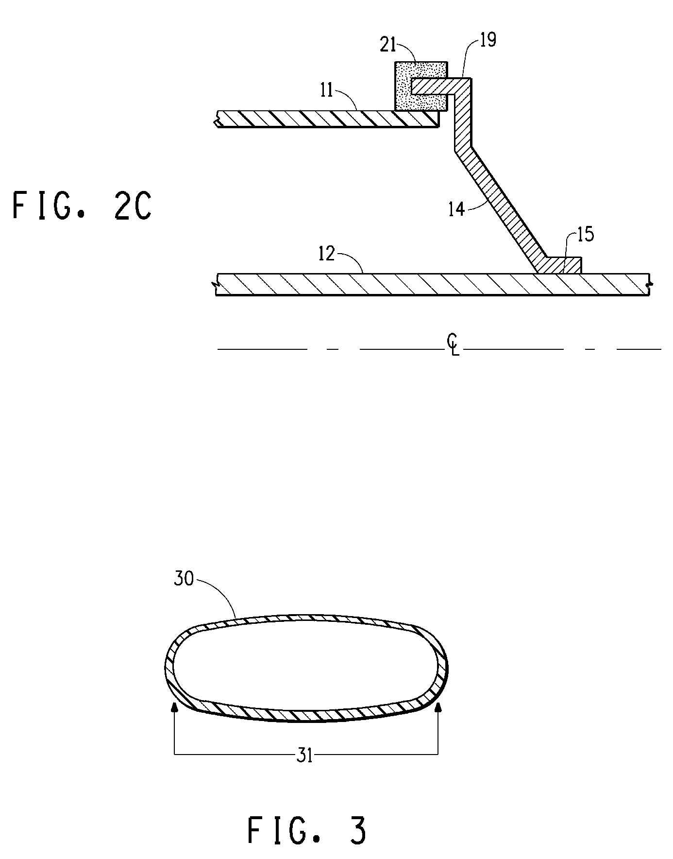
Mufflers having polymeric bodies that are protected from being overheated from the exhaust pipe by having an air gap between the exhaust pipe and the polymeric body are disclosed. Also disclosed is a process for making muffler systems wherein the muffler polymeric bodies have a cross section that is constant over the length of the muffler polymeric body. The muffler systems are inexpensive to make and install.

Description

FIELD OF THE INVENTION[0001]Mufflers have polymeric bodies which have an air gap between the polymeric body and the exhaust pipe at and / or near their mounting points to the exhaust pipe is disclosed as well as a process for manufacturing muffler systems by extrusion of polymeric muffler bodies.TECHNICAL BACKGROUND[0002]Mufflers (also called silencers) are used as part of exhaust systems of internal combustion and other types of engines, principally to reduce the noise exiting the engine with the exhaust gases (except perhaps in jet and rocket engines). Typical types of uses for these systems are on automobiles, trucks, snowmobiles, motorcycles, boats, scooters, railroad engines, electrical generators, golf carts, tractors and other motorized agricultural equipment, lawn mowers and other power landscaping equipment, etc. Virtually any use for an internal combustion engine usually also includes a muffler (system). Because of the high temperatures of the exhaust gases, and the corrosiv...

Claims


Application Information

Patent Timeline
Patent Type & Authority Applications(United States)
IPC IPC(8): F01N1/00B23P17/00F01N13/16F01N13/18
CPCF01N1/24F01N13/143F01N13/16Y10T29/49398F01N13/1888F01N2530/18F01N13/1838
Inventor LEBOEUF, PHILIPPEBONNIN, FREDERICMAURER, KARL PAULJONES, DANIEL P.
Owner EI DU PONT DE NEMOURS & CO
Learn More