Method for safe filling with carbon nanotubes, filling system and industrial plant employing this method

a carbon nanotube and filling system technology, applied in the direction of water supply installation, liquid handling, packaging goods type, etc., can solve the problems of unsuitable carbon nanotube transfer devices, increased risk, soiling and malfunction, etc., and achieve the effect of high safety and tight sealing

Active Publication Date: 2009-08-06
ARKEMA FRANCE SA
View PDF12 Cites 11 Cited by
  • Summary
  • Abstract
  • Description
  • Claims
  • Application Information

AI Technical Summary

Benefits of technology

[0017]Thus, in order to provide the maximum level of safety for transferring carbon nanotubes and to afford an industrial solution to the transfer of CNTs from one site to another, the applicant has chosen to fit the containers with double-valve devices such as, for example, a device of the “Buck®” or “Glatt®” type. These devices are also known by the name of butterfly valves. These are compact devices in the form of two flat cylindrical elements that are very compact and seal very tightly. Each element constitutes one valve, one being known as the active valve and the other as the passive valve.
[0019]Such devices comprise an active first valve and a passive valve. The opening control is on the periphery of the active valve of the device. The double-valve device can be opened only when the two valves are coupled to one another. The opening control is locked when there is no coupling. The passage between two receptacles connected to one another by this type of valve is opened and closed by shutters that face one another and pivot about a diametral axis under the action of the opening control. The faces of the shutters that are in contact with the products contained in the receptacles are never in contact with the outside. Thus, after the two valves have been disconnected, no product (powder or the like) is present on the external faces of the shutters. This then protects the environment while products are being transferred and even afterwards.

Problems solved by technology

In any event, that transfer device is unsuited to carbon nanotubes because, being inside the container, the drive mechanism that drives the valve is in contact with the powder that is to be transferred.
There is therefore a risk of soiling and of malfunctioning, which risk increases as the powder that is to be transferred becomes more fine, and nanoparticles such as carbon nanotubes are extremely fine.
Further, that device is ill suited to an industrial method for filling with carbon nanotubes because the device entails containers that are specially adapted to take external controls so that the movement of the cone valve can be actuated.

Method used


Image

  • Method for safe filling with carbon nanotubes, filling system and industrial plant employing this method
  • Method for safe filling with carbon nanotubes, filling system and industrial plant employing this method
  • Method for safe filling with carbon nanotubes, filling system and industrial plant employing this method

Examples


Embodiment Construction

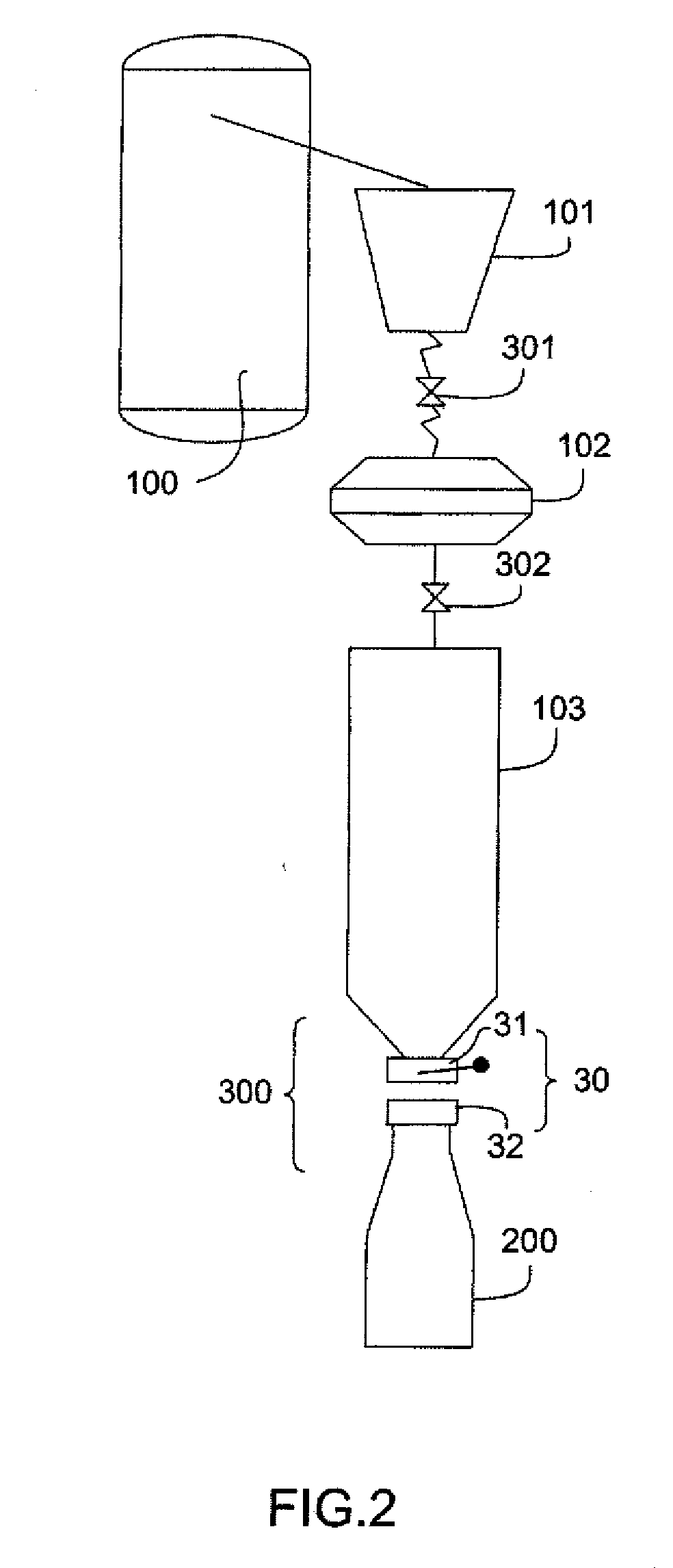
[0035]Large-scale handling of CNTs has lead the applicant to develop an industrial plant covering the phases from manufacture, that is to say from the reactor in which the CNTs are formed, to the packaging of CNTs in containers, the sizes of which vary from 201 to 20001 depending on the anticipated end-use.

[0036]The present invention falls into the context of this development and applies to the transfer of CNTs from one receptacle to another when one receptacle needs to be mechanically coupled to another, either directly or via an outlet line, whether this be a packaging receptacle or any other receptacle, for example a metering receptacle.

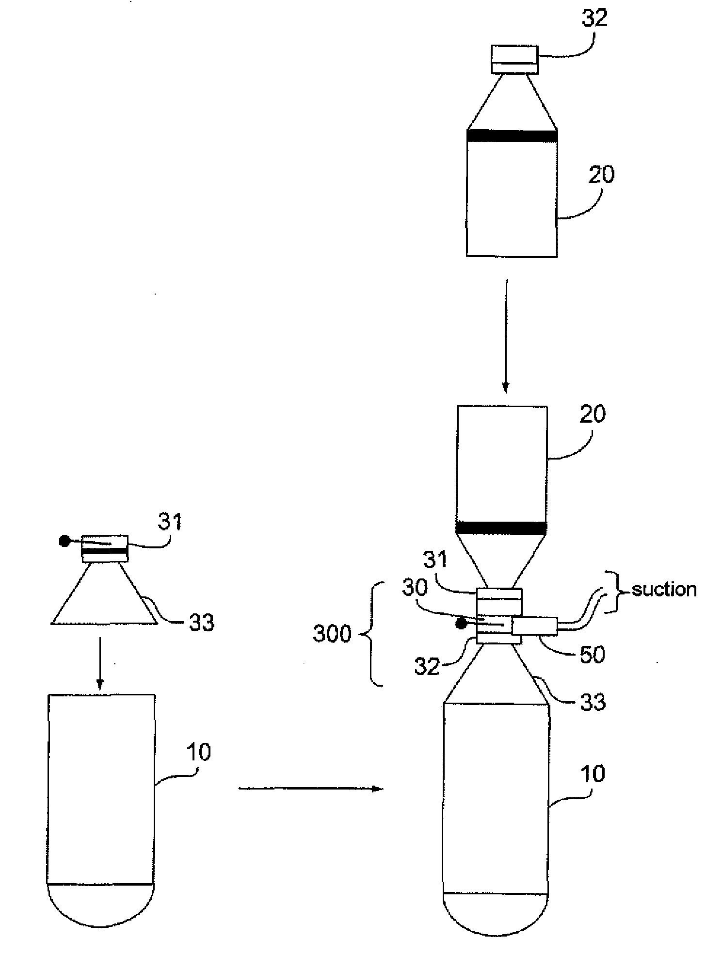
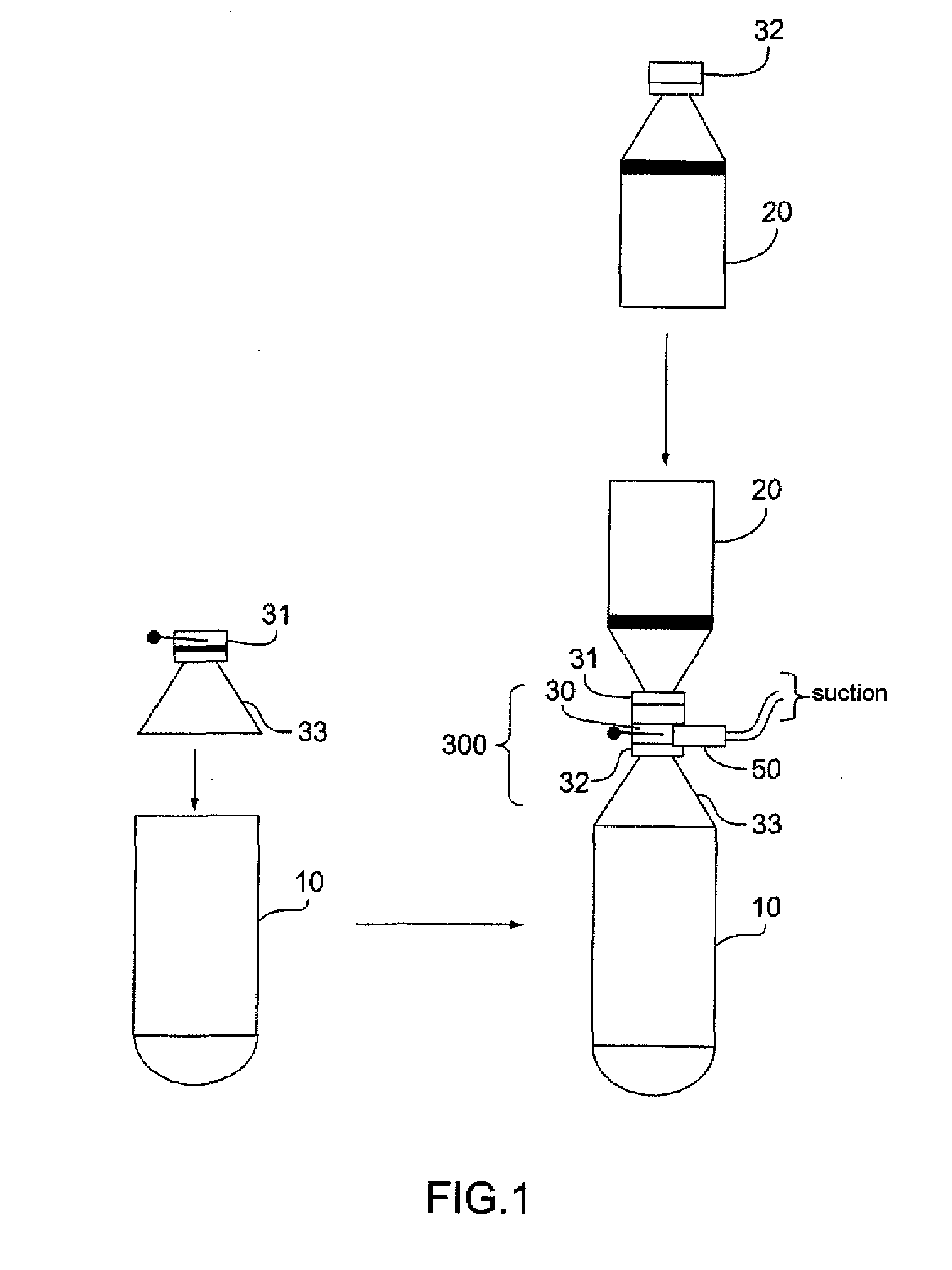
[0037]The description given hereafter illustrates the use of the method according to the invention in two applications and the system used for implementing the method.

[0038]In a first application illustrated by the diagram that is FIG. 1, the method and the implementation system allow CNTs to be transferred to a receptacle 20 from another receptac...


PUM

PropertyMeasurementUnit
lengthaaaaaaaaaa
lengthaaaaaaaaaa
mean diameteraaaaaaaaaa

Abstract

The invention relates to a method for filling a receptacle (200) with carbon nanotubes from another receptacle (106) whereby the CNTs are passed from one receptacle to the other by means of a coupling (300) comprising a double-valve device (30), each valve being coupled to one of the receptacles, the valves (31, 32) closing independently and tightly and being openable only when they are coupled to one another.

Description

[0001]The invention relates to an industrial method for safely filling a receptacle with carbon nanotubes (CNT) from another receptacle. The invention also relates to a filling system employing the method. The invention also relates to a plant for the safe packaging of carbon nanotubes, which is equipped with a filling system according to the invention.FIELD OF THE INVENTION[0002]Carbon nanotubes (CNT) are particles of a diameter ranging between 0.4 nm and 50 nm and of a length in excess of 100 times their diameter. CNTs form bundles such that they exist in the form of a powder of a range of particle sizes in which the mean diameter of the particles is about 400 microns.[0003]The expansion in activity relating to CNTs has lead the applicant, in their capacity as a CNT manufacturer, to handle significant quantities of CNT powder and to seek solutions to allow CNTs to be packaged into containers and transported between reactor and storage hopper. However, handling CNTs and designing s...

Claims


Application Information

Patent Timeline
Patent Type & Authority Applications(United States)
IPC IPC(8): B65B1/04B65B1/16B65B1/30B65B57/00
CPCB65B1/28B65B1/16B65G69/183B65G69/182Y10T137/87925B82B3/00C01B32/168B82Y40/00C08K3/041
Inventor BORDERE, SERGEGAILLARD, PATRICE
Owner ARKEMA FRANCE SA
Why Eureka
Try Eureka