
Space-time/space-frequency coding for multi-site and multi-beam transmission

a multi-site and multi-beam technology, applied in the field of spacetime/spacefrequency coding for multi-site and multi-beam transmission, can solve the problems of difficult to achieve high data rate to these mts, interference to the reception of the other stream, and macro-diversity techniques from 3g are therefore not directly applicable to these future systems, so as to improve throughput and coverage in cellular systems

Active Publication Date: 2009-07-30
KONINKLJIJKE PHILIPS NV
View PDF16 Cites 10 Cited by
  • Summary
  • Abstract
  • Description
  • Claims
  • Application Information

AI Technical Summary

Benefits of technology

[0013]An object of the present invention is to provide transmission scheme with improved throughput and coverage in cellular systems.
[0015]Accordingly, in a cellular system where the same data is to be transmitted to one or more mobile terminals from more than one cell-site, at least one of a space-time and space-frequency coding is applied to the data from more than one cell-site. This means that identical data portions or blocks transmitted from different antennas may have a different transformation applied by the coder. Thus, increased user throughput at cell edge and increased cell throughput can be achieved by supporting more active users close to the cell-edge. This also leads to a better coverage.
[0021]The necessary channel knowledge can be achieved by associating a specific (and known), and preferably orthogonal, pilot sequence with each part of the space-time block code. This allows the receiver to make a channel estimate corresponding to the channels for each antenna sending a particular part of the space-time or space-frequency code.

Problems solved by technology

Cell edge MTs therefore experience strong interference in addition to low signal to noise ratio (SNR), which makes it difficult to achieve high data rates to these MTs.
However, each wanted data stream causes interference to the reception of the other stream.
The macro-diversity techniques from 3G are therefore not directly applicable to these future systems.
This approach improves the inter-cell interference situation for cell-edge MTs at the expense of increasing the frequency re-use factor, which results in lower spectral efficiency than re-using all subcarriers in all parts of every cell (i.e., frequency re-use factor of one).
It may also reduce the peak throughput to cell-edge users since only a subset of the total number of subcarriers are available for use.
The downside of this approach is of course that this consumes resources (subcarriers) in two or more cells for the benefit of one MT.
However, although the SFN concept means that a simple receiver can be used, the combined signal can still undergo fading.

Method used


Image

  • Space-time/space-frequency coding for multi-site and multi-beam transmission
  • Space-time/space-frequency coding for multi-site and multi-beam transmission

Examples


first embodiment

[0030] an OFDM broadcast downlink is provided in a UMTS LTE network. Each of several cell-sites (corresponding to a base station device or enhanced Node B (E-Node B) in 3G terminology) supports transmissions from more than one antenna, each arranged to cover overlapping geographical areas.

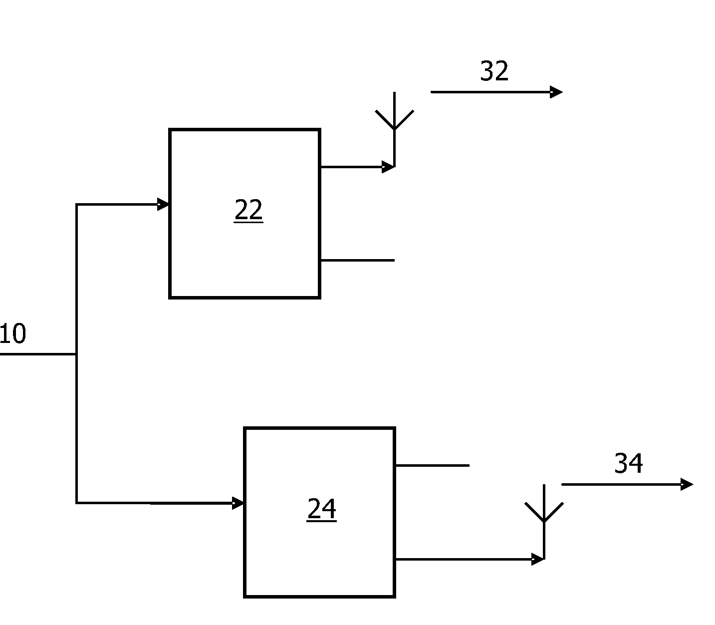
[0031]FIG. 2 shows a schematic block diagram of a transmission arrangement according to the first embodiment with multiple transmission sites. An input signal 10 is supplied to each of a first space-time coder 22 which generates a first part 32 of a transmission signal and a second space-time coder 24 which generates a second part 34 of the transmission signal.

[0032]The transmissions from the same cell-site are synchronized, and the cell-sites are synchronized with each other over an extended geographical area. The synchronization may apply at both OFDM symbol level and frame level.

[0033]Furthermore, the same predetermined synchronization sequence (or data pattern) is transmitted from all the anten...

second embodiment

[0045] an OFDM macro-diversity scheme is provided in a UMTS LTE network.

[0046]The second embodiment is similar to the first embodiment, except that the transmission is intended for a particular MT, and the signals are transmitted from a limited number of cell sites (or antennas at one cell site), e.g., an active set allocated to the MT. The different transmissions have different parts of a space-time block code applied.

third embodiment

[0047] the proposed scheme is applied to UMTS Wideband CDMA (WCDMA) system with beamforming (e.g., by two virtual antennas) and common pilots.

[0048]In the third embodiment the Alamouti space-time block code can be applied and each of the two parts of the space-time block code is transmitted using a different beam (i.e. different virtual antennas). The physical antennas of the beamforming array are located at the same site. At the receiver the required channel estimates are derived from measurements of two orthogonal common pilot signals transmitted from different physical antennas (not beamformed), together with knowledge of the beamforming weights which are transmitted on a separate signaling channel.


PUM


Abstract

The present invention relates to space-time or space-frequency coding in cellular systems. The same data is transmitted from different antennas with different coverage areas, corresponding to different cells. The different data streams have different parts of the space-time block codes applied. A mobile terminal can combine the different parts of the space-time block codes in different received signals. This provides better performance than the known techniques for single frequency networks. The invention can also be applied to antennas with different coverage areas from the same site, and different beams formed with antenna arrays.

Description

FIELD OF THE INVENTION[0001]The present invention relates to a method, system, transmitter and receiver for using at least one of space-time and space-frequency codes in a cellular system. In a particular example, the present invention relates to a multi-site and multi-beam transmission system. Moreover, the present invention relates to a computer program product for carrying out the afore-mentioned method.BACKGROUND OF THE INVENTION[0002]One of the aims of future cellular wireless communication systems is to enhance the achievable data throughput to mobile terminals (MT) situated close to a cell edge. This is important as, assuming a reasonably uniform distribution of MTs over the cell area, then a significant fraction of the MTs in a cell is close to its periphery. When the same carrier frequency is re-used in neighboring cells, the signal from the ‘wanted’ base station (BS) with which the MT is communicating is received at the cell edge at power levels similar to signals originat...

Claims


Application Information

Patent Timeline
Patent Type & Authority Applications(United States)
IPC IPC(8): H04L27/28H04L27/00H04L27/06H04B7/02
CPCH04B7/0617H04B7/0669H04L27/2675H04L5/001H04L27/2649H04W52/42H04L1/0606H04L1/0618H04L27/2655H04L25/0224
Inventor MOULSLEY, TIMOTHY JAMESROBERTS, D. K.BAKER, MATTHEW PETER JOHNWEI, XUSHENG
Owner KONINKLJIJKE PHILIPS NV
Learn More