
High Voltage Inverter

a high-voltage inverter and high-voltage technology, applied in the field of inverters, can solve the problems of large bank of parallel connected solid-state devices, environmental hazards of mercury vapor tubes, solid-state devices having the drawback of being dangerous, etc., and achieve the effect of high reliability

Active Publication Date: 2009-07-30
ADVANCED FUSION SYST LLC
View PDF13 Cites 26 Cited by
  • Summary
  • Abstract
  • Description
  • Claims
  • Application Information

AI Technical Summary

Benefits of technology

[0015]Preferred embodiments of the foregoing inverter include the function of converting DC power to AC power, while having a low number of parts, exhibiting high reliability, and not being environmentally dangerous.

Problems solved by technology

Mercury vapor tubes have the drawback of being environmentally dangerous if the mercury vapor in the tubes escapes into the environment.
Solid state devices have the drawback of comprising large banks of many parallel connected, solid state devices such as thyristors (e.g., silicon-controlled rectifiers).

Method used


Image

  • High Voltage Inverter
  • High Voltage Inverter
  • High Voltage Inverter

Examples


Embodiment Construction

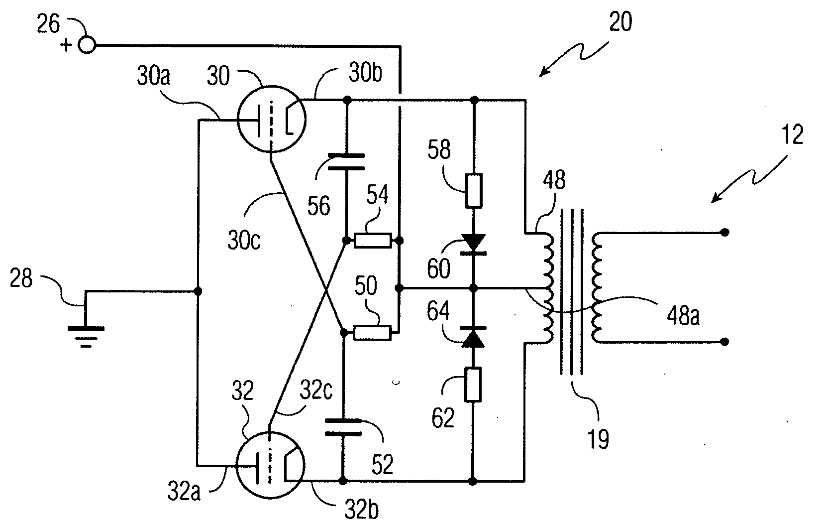
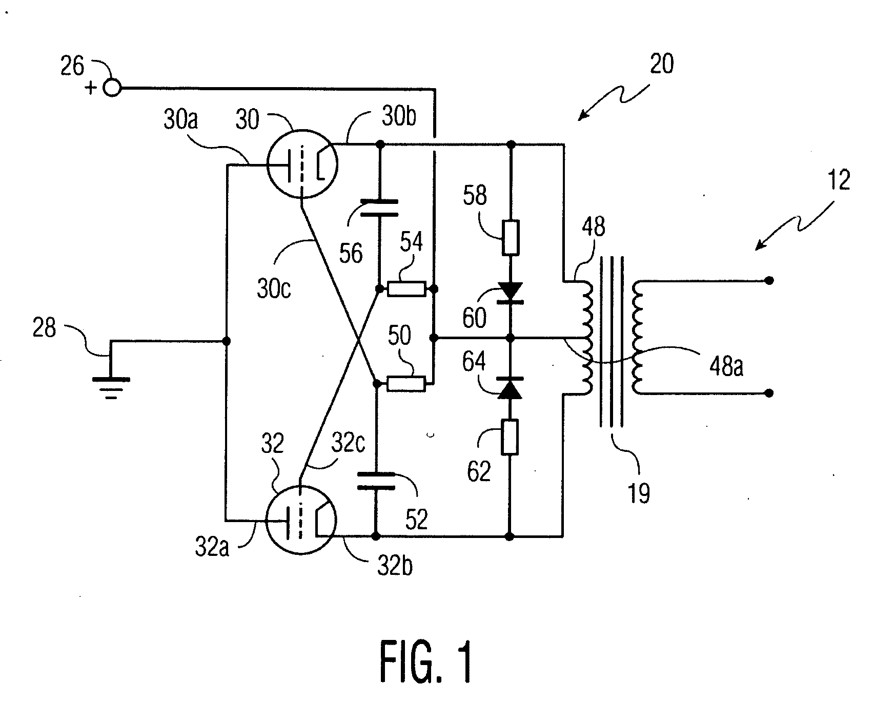
[0016]FIG. 1 shows a preferred high voltage inverter 10 for converting high voltage DC to AC current. The output of inverter 10 preferably provides a voltage in excess of 10 KV and with an AC frequency in the range of from about 50 to 400 cycles per second. Input AC phase 20 converts to AC high voltage DC that is supplied between input node 26 and a ground 28.

[0017]The following description covers the areas of (1) AC input phases of the high voltage inverter of the present invention, (2) a high voltage inverter incorporating phase synchronization, and phase monitoring and power balancing of an electrical power distribution grid, and (3) a high voltage DC to DC inverter.

1. AC Input Phase

[0018]Input AC phase 20 of FIG. 1 includes cold cathode field emission controllable electron tubes 30 and 32 of triode structure. Alternatively, such electron tubes could be replaced with tubes of tetrode or pentode structure with appropriate adjustments to the circuitry as would be obvious to a perso...


PUM


Abstract

Disclosed is a high voltage inverter for converting DC power to AC power with one or more AC output phases. The inverter has for each AC output phase an AC input phase circuit comprising first and second cold cathode field emission controllable electron tubes of triode, tetrode or pentode structure. Each electron tube has a first input node for connection to a high voltage DC potential in excess of 20 KV and a second input node for connection to ground. First electron tube is serially connected between a first end of a primary winding and ground, and second electron tube is serially connected between a second end of the primary winding and ground. Control circuitry controls the electron tubes so that the first and second electron tubes alternatively conduct so as to alternately bring the first and then second end of the primary winding approximately to the potential of ground.

Description

FIELD OF THE INVENTION[0001]The present invention relates to inverters including the function of converting DC power to AC power, and more particularly to high voltage inverters wherein input DC voltages exceed 20 KV.BACKGROUND OF THE INVENTION[0002]Prior art inverter technologies for converting DC at voltages exceeding 20 KV to AC power include Mercury vapor tubes and solid state devices. Both technologies have drawbacks that would be desirable to avoid.[0003]Mercury vapor tubes have the drawback of being environmentally dangerous if the mercury vapor in the tubes escapes into the environment. Solid state devices have the drawback of comprising large banks of many parallel connected, solid state devices such as thyristors (e.g., silicon-controlled rectifiers). Apart from the cost factor and complications of requiring many parallel-connected devices, reliability is reduced because the probability of one of many component devices failing greatly exceeds the probability of a single de...

Claims


Application Information

Patent Timeline
IPC IPC(8): H02M7/48
CPCH02M7/53832H02M7/533H02M7/51H01J21/10
Inventor BIRNBACH, CURTIS
Owner ADVANCED FUSION SYST LLC
Learn More