
Tank opening-closing device

a technology of opening and closing of tanks, which is applied in the direction of machines/engines, liquid handling, packaging goods types, etc., can solve the problems of high number of parts, complex mechanism, poor operability of fuel caps, etc., and achieve the effect of simple constitution

Inactive Publication Date: 2009-07-30
TOYODA GOSEI CO LTD
View PDF15 Cites 17 Cited by
  • Summary
  • Abstract
  • Description
  • Claims
  • Application Information

AI Technical Summary

Benefits of technology

The present invention provides a tank opening-closing device for fuel tank vehicles that has a simple constitution and is easy to operate. The device includes a tank opening forming member with an inlet, a valve opening-closing mechanism, and a valve support moving body that can slide in the opening and closing direction. The valve opening-closing mechanism can be moved from a closing position to a fueling position to regulate the internal pressure of the fuel tank during fueling. The device also includes a retraction mechanism that can be operated with a fueling gun or external force to open and close the inlet. The valve opening-closing mechanism functions as both an opening and closing valve and a pressure adjustment valve, so it is not necessary to provide multiple valves and springs, reducing the number of parts and simplifying the device. The valve support moving body is supported to move in the opening and closing direction, and a shutter mechanism can be used to close the opening when not during fueling. The invention provides a tank opening-closing device that is easy to use, reduces the number of parts, and ensures sealing integrity.

Problems solved by technology

This kind of fuel cap not only has poor operability because a plurality of rotation operations is required when fueling, but there was also the problem that when removed, it was necessary to come up with a means for remembering the place one left it or for preventing loss.
However, with the flap valve mechanism, when the pressure adjustment valve is attached to the flap valve, not only does the mechanism become complex, but there was also the problem that the number of parts becomes high.

Method used


Image

  • Tank opening-closing device
  • Tank opening-closing device
  • Tank opening-closing device

Examples


first embodiment

A. First Embodiment

(1) Schematic Constitution of the Tank Opening and Closing Device

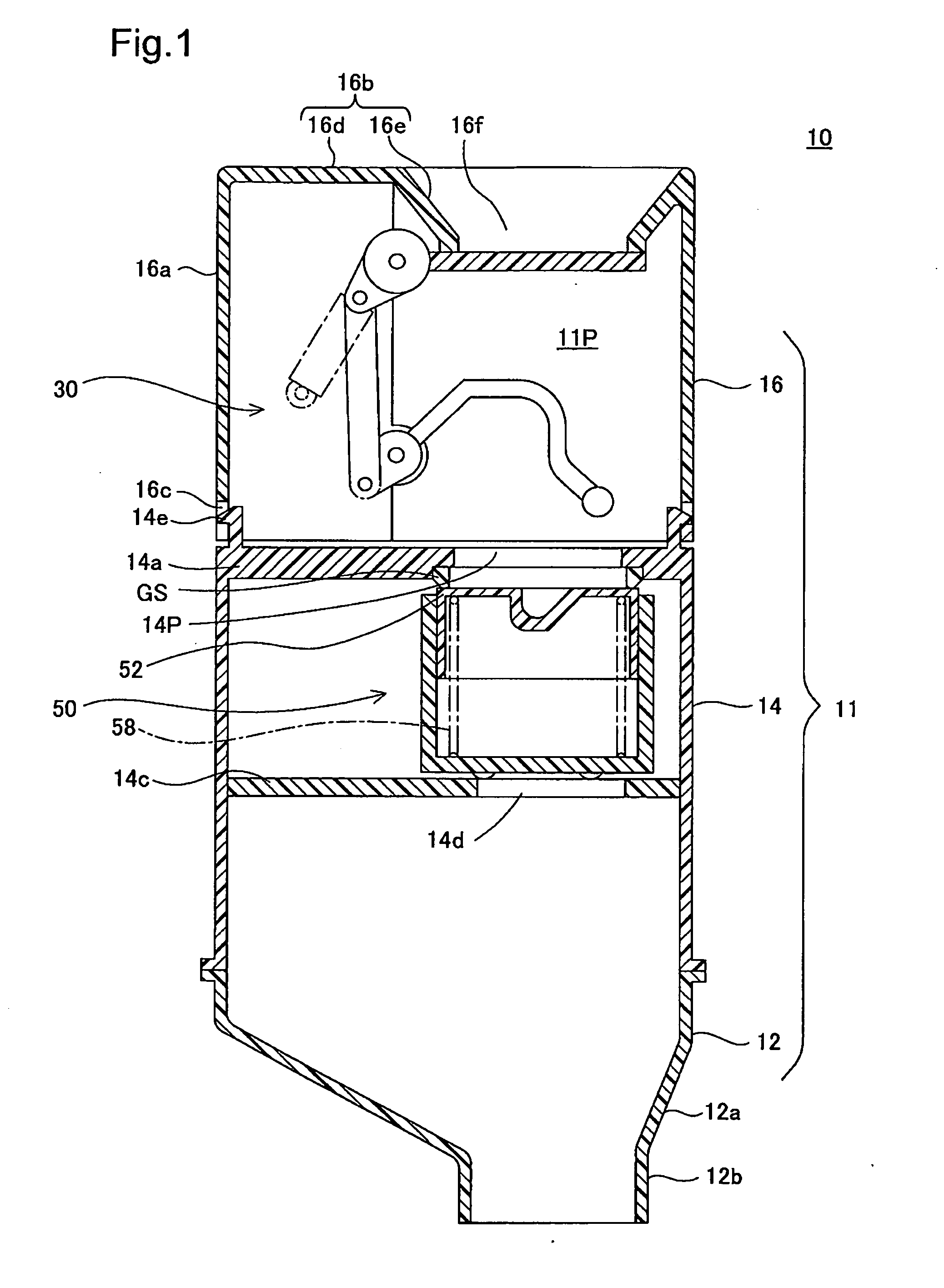
[0067]FIG. 1 is a cross section view of the axial direction of the tank opening-closing device of the first embodiment of the present invention. The tank opening-closing device 10 does not use a fuel cap, and is a mechanism for supplying fuel to the fuel tank, in other words, by opening and closing the fuel path with an external force or the like from a fueling gun after the fueling lid is opened, is a mechanism for supplying fuel to the fuel tank (not illustrated) from the fueling gun. Following, we will describe the detailed constitution of the tank opening-closing device.

(2) Constitution of Each Part

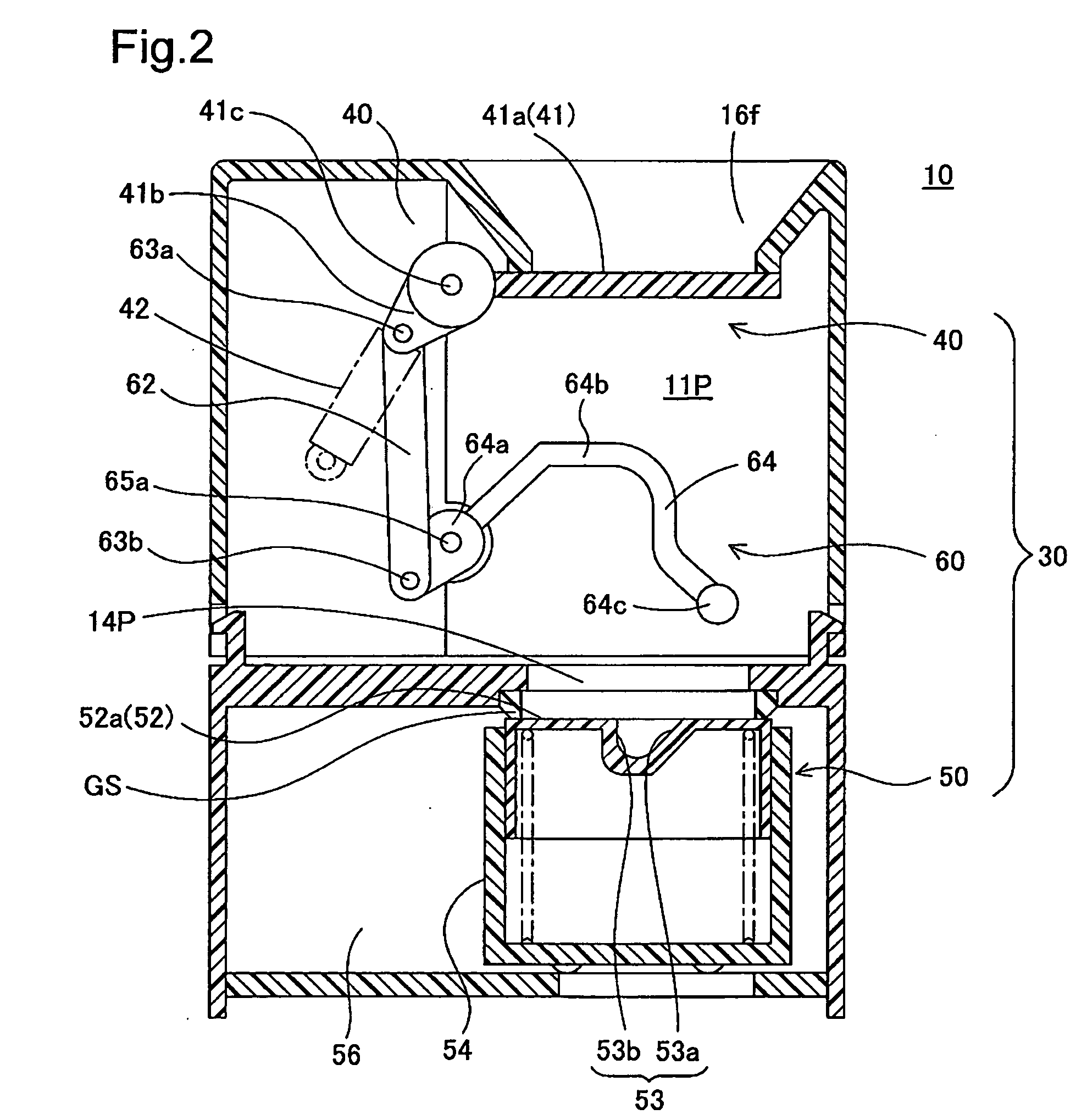
[0068]The tank opening-closing device 10 is equipped with the tank opening forming member 11 which has a fuel path 11P connected to the fuel tank, and an opening-closing mechanism 30 for opening and closing the fuel path 11P.

(2)-1 Tank Aperture Forming Member 11

[0069]The tank opening forming member 11 ...

second embodiment

B. Second Embodiment

[0085]FIG. 8 and FIG. 9 are cross sections of the second embodiment, with FIG. 8 showing the state when the tank opening-closing device is closed, and FIG. 9 showing the state when the tank opening-closing mechanism is open. The opening-closing mechanism 30B of the embodiment has simplified the shutter mechanism and the linking mechanism constitution, and has a special feature of a spring mechanism that returns the valve opening-closing mechanism 50B. Specifically, the opening-closing mechanism 30B is equipped with an operating member 64B, a spring 42B, and a valve opening-closing mechanism 50B. The operating member 64B has the same shape as the operating member of the first embodiment, and is equipped with the rotating support unit 64Ba, the arm 64Bb, and the pressing body 64Bc. The rotating support unit 64Ba is supported to be able to rotate on the support body 17B, and the arm 64Bb is arranged facing the opening 16Bf. With the operating member 64B, the operati...

third embodiment

C. Third Embodiment

[0088]FIG. 10 is a cross section view showing the opening-closing mechanism of the third embodiment. A special feature of the constitution of the opening-closing mechanism 30C of the embodiment is that the constitutions of the shutter mechanism 40C and the linking mechanism 60C is simplified. Specifically, the shutter mechanism 40C is equipped with the opening and closing member 41C. The opening and closing member 41C is equipped with a disk part 41Ca that opens and closes the opening 16Cf, and a rotating support part 41Cb pivoted at the support body 17C at the end part of the disk part 41Ca. The linking mechanism 60C is equipped with an operating member 64C and a spring 42C that biases the spring force in the direction of closing the operating member 64C. FIG. 11 is a perspective view showing the opening and closing member 41C and the operating member 64C seen from below. The operating member 64C has almost the same shape as the operating member 64C of the first ...


PUM

PropertyMeasurementUnit
angleaaaaaaaaaa
internal pressureaaaaaaaaaa
rotation forceaaaaaaaaaa

Abstract

The tank opening-closing device is realized with a simple constitution of the opening-closing mechanism equipped with a pressure adjustment valve for regulating the internal pressure of the fuel tank. The opening-closing mechanism is equipped with a gasket provided on the opening peripheral edge part of the inlet of the tank opening forming member, the valve opening-closing mechanism for opening and closing the inlet and also regulating the internal pressure of the fuel tank, and a retraction mechanism that selectively moves the valve opening-closing mechanism to the closing position and the fueling position in conjunction with the fueling gun, The valve opening-closing mechanism has a closing position for opening and closing the inlet and a fueling position retracted from the inlet for which it is possible to supply fuel.

Description

CROSS REFERENCE TO RELATED APPLICATIONS[0001]This application is a U.S. national stage application of PCT / JP2007 / 065311 filed on Jul. 30, 2007, and claims priority to, and incorporates by reference, Japanese Patent Application No. JP2006-206252 filed on Jul. 28, 2006.TECHNICAL FIELD[0002]The present invention relates to a tank opening-closing device for fueling a fuel tank through a fuel path, and particularly relates to a mechanism for opening and closing the fuel path.BACKGROUND ART[0003]The inlet of the inlet pipe for fueling an automobile is typically sealed by a fuel cap that is attached and detached by a rotation operation. This kind of fuel cap not only has poor operability because a plurality of rotation operations is required when fueling, but there was also the problem that when removed, it was necessary to come up with a means for remembering the place one left it or for preventing loss. To address this kind of problem, arts for which a flap valve mechanism is provided on...

Claims


Application Information

Patent Timeline
Patent Type & Authority Applications(United States)
IPC IPC(8): B60K15/04
CPCB60K15/04B60K2015/0429F16K24/00F02M37/0011B60K2015/0445
Inventor HAGANO, HIROYUKINAKAGAWA, MASAYUKI
Owner TOYODA GOSEI CO LTD
Learn More