
Silent chain

Inactive Publication Date: 2009-07-23
TSUBAKIMOTO CHAIN CO
View PDF9 Cites 9 Cited by
  • Summary
  • Abstract
  • Description
  • Claims
  • Application Information

AI Technical Summary

Benefits of technology

[0011]We have determined that, if the connecting pin comes into uniform contact with the inner peripheral surfaces of the pin holes of all the toothed link plates when the connecting pin is bent as a result of a high tensile load applied to the chain, the load applied to all the toothed link plates can be equalized, and local wear, chain wear elongation, and rupture of the pin holes and the connecting pins can be suppressed.
[0013]The above-described bent configuration of the connecting pins equalizes the surface pressures acting between the connecting pins and the inner circumferential surfaces of the pin holes in the toothed link plates. Equalization of surface pressures prevents rupture of individual link plates. Equalization of surface pressures also suppresses wear of the inner circumferential surfaces of the pin holes and of the connecting pins, and thereby reduces wear elongation of the chain, and suppresses noises generated as a result wear elongation.
[0014]Preferably, the toothed link plates in each guide row through which each connecting pin extends are aligned with one another, and the pin holes of the toothed link plates in each non-guide row through which the same connecting pin extends are also aligned with one another. Thus, when tension is applied to the chain, the connecting pins can be substantially straightened and brought into uniform contact with the pin holes of the toothed link plates of the guide rows and into uniform contact with the pin holes of the toothed link plates of the non-guide rows. When a high tensile load is applied to the chain, the loads applied to the individual toothed link plates are equalized and the stress balance of the toothed link plates is improved.
[0015]In the preferred embodiment, all the pin holes of the toothed link plates in the guide rows have the same inside diameter, and all the pin holes of said toothed link plates in the non-guide rows have the same inside diameter. Thus, the toothed link plates of the guide rows can be made according to a unified standard, and the toothed link plates of the non-guide rows can also be made according to a unified standard. As the result, the manufacture of the silent chain can be simplified.

Problems solved by technology

In addition measurements of abrasion wear showed the wear of the pin holes in the outermost plates of the non-guide rows was significantly greater than the wear found in the pin holes of the other plates.

Method used


Image

  • Silent chain
  • Silent chain
  • Silent chain

Examples


Embodiment Construction

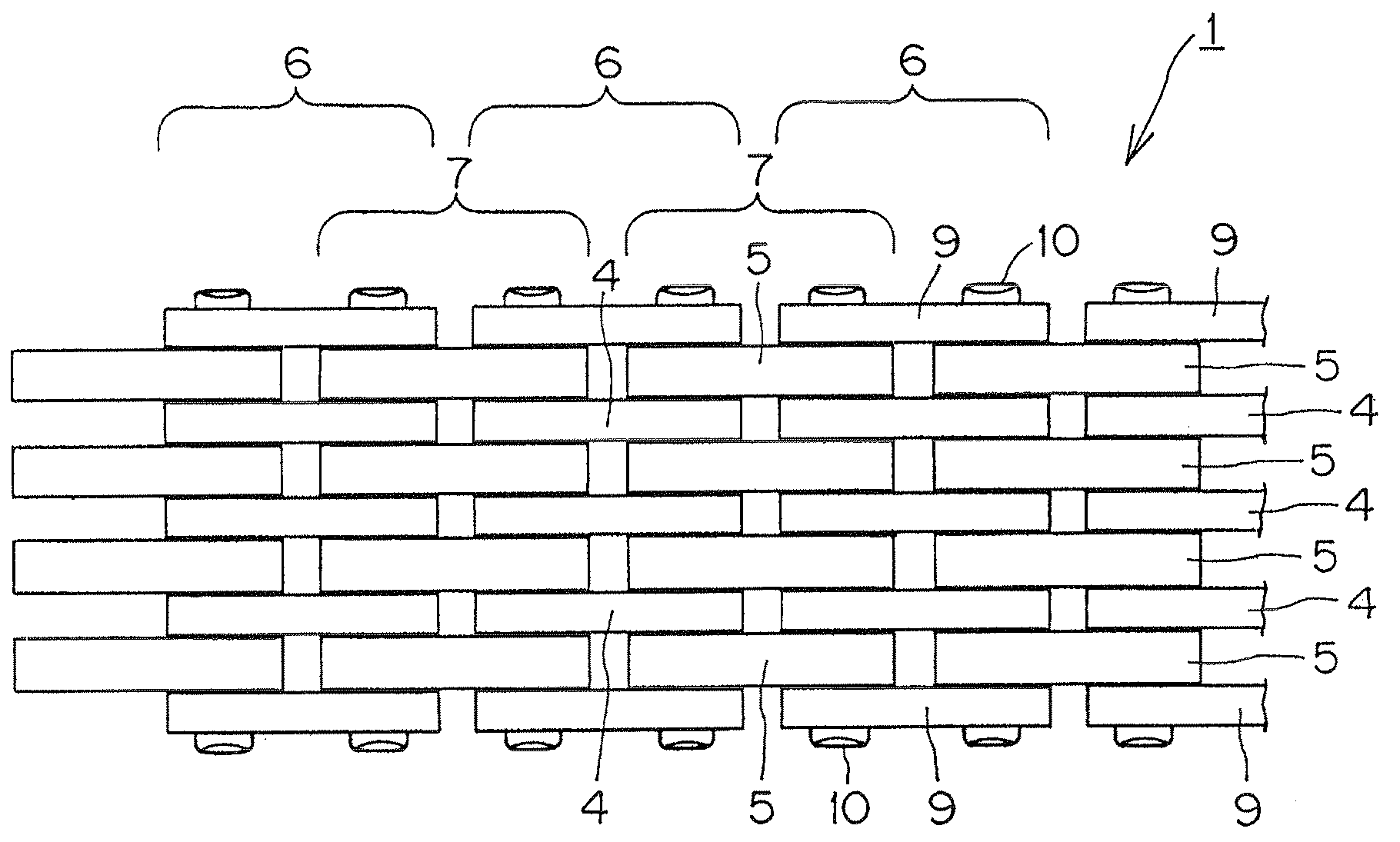
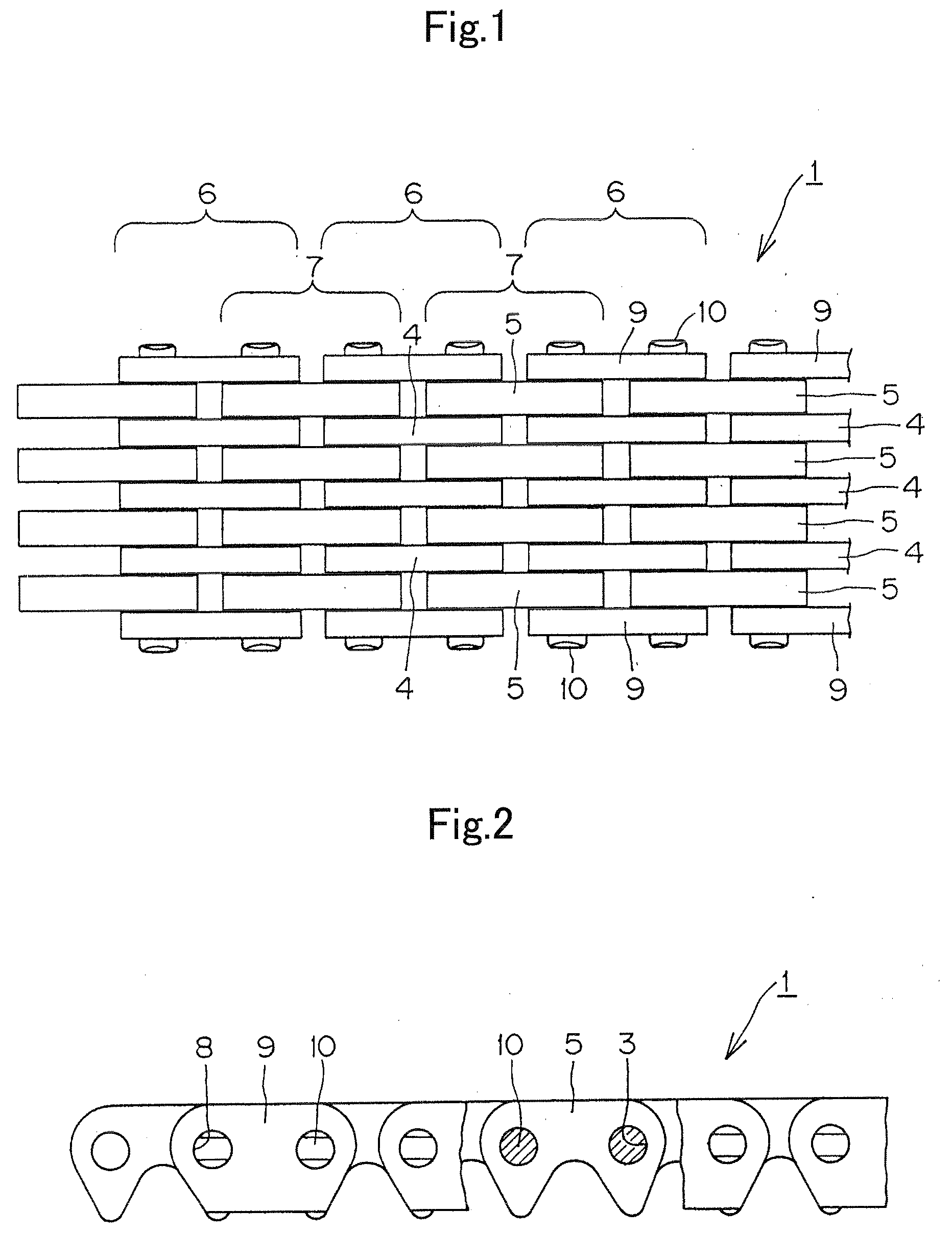
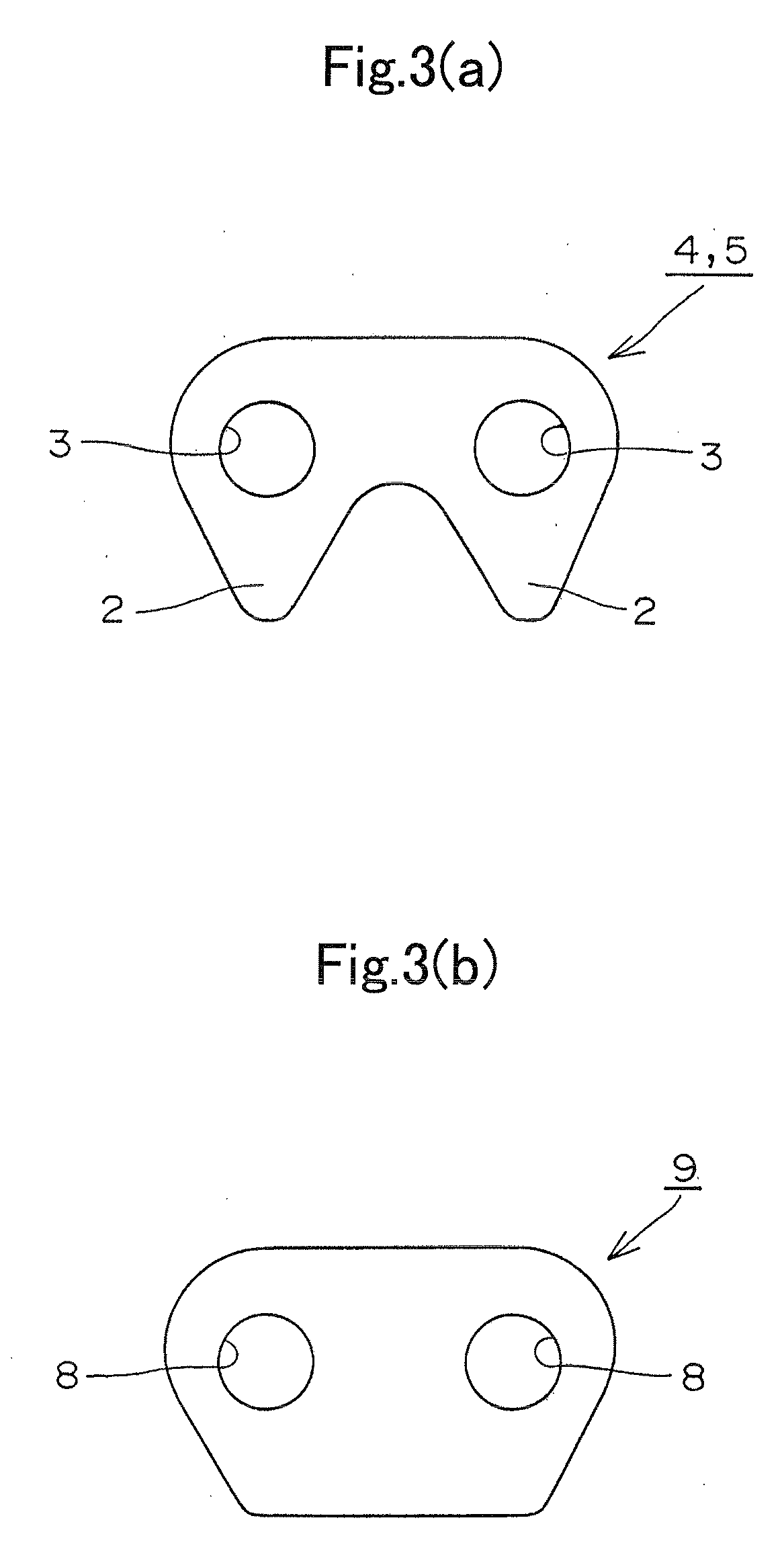
[0024]As shown in FIGS. 1 and 2, an endless silent chain 1 according to the invention comprises interleaved inner plates 4 and 5, and guide plates 9. As shown in FIG. 3(a), each of the inner plates is formed with a pair of teeth 2, and a pair of pin holes 3. The inner plates 4 are arranged in guide rows 6 between a pair of guide plates 9 on the outermost sides of the chain. Inner plates 5, which form the non-guide rows 7 of the chain, are interleaved with the plates 4 and 9. Connecting pins 10 are press-fit into pin holes 8 of the guide plates 9. These connecting pins fit loosely in pin holes 3 of the inner plates 4 and 5.

[0025]In the silent chain 1, the number of plates in a guide row 6 (three toothed link plates 4 and two guide plates 9, for a total of five) is larger than the number (four) of the plates in a non-guide row 7, as in a conventional silent chain. To balance the strengths of the guide rows 6 and the non-guide rows 7, the plates 4 and 9 in the guide rows 6 are made thi...


PUM


Abstract

In a silent chain, interleaved toothed link plates in guide rows and non-guide rows are articulably connected by connecting pins fixed to guide plates at the outer ends of the guide rows. In each guide row, the connecting pins are bent in such a way that the central portions of the connecting pins are closer to each other than the end portions when the chain is under moderate tension or no tension. As greater tension is applied to the chain, the bent connecting pins become substantially straight and are brought into substantially uniform contact with pin holes in the plates.

Description

CROSS REFERENCE TO RELATED APPLICATION[0001]This application claims priority on the basis of Japanese patent application 2008-008151, filed Jan. 17, 2008. The disclosure of Japanese application 2008-008151 is hereby incorporated by reference.FIELD OF THE INVENTION[0002]The invention relates to a silent chain of the kind used in a power transmission mechanism in an automobile engine, an industrial machine, a transfer mechanism or the like. The silent chain according to the invention can be used, for example, as a timing chain in an automobile engine, for transmitting power from a crankshaft sprocket to one or more valve-operating camshaft sprockets.BACKGROUND OF THE INVENTION[0003]A typical silent chain is in the form of an endless loop and comprises alternating guide rows and non-guide rows of plates. Each of the guide rows comprises a pair of guide plates and a plurality of toothed link plates disposed between the guide plates. Each of the non-guide rows comprises a plurality of to...

Claims


Application Information

Patent Timeline
IPC IPC(8): F16G13/06
CPCF16G13/08F16G13/04
Inventor TOHARA, TAKASHI
Owner TSUBAKIMOTO CHAIN CO
Learn More