
System and Method for Heat Energy Conservation Via Corner Reflectors

Inactive Publication Date: 2009-07-23
MYERS BLAINE E
View PDF13 Cites 10 Cited by
  • Summary
  • Abstract
  • Description
  • Claims
  • Application Information

AI Technical Summary

Benefits of technology

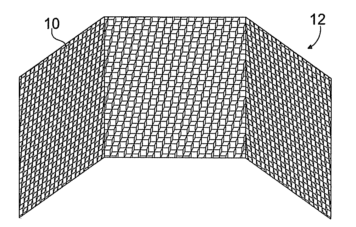
[0011]Specifically, the present invention includes the use of infrared retro-reflective surfaces, namely one or more corner reflector arrays, situated near the individual that desires to feel warmer than the ambient environment temperature would otherwise permit. The corner reflector array offers high reflectivity in the infrared energy band, thereby, causing the individual's heat energy to bounce back to the individual, and making them feel warmer than they would if they were only subject to the ambient environment temperature. The present invention allows the individual to stay warm while not expending any energy costs or CO2 emissions that are normally associated with prior art systems and methods of keeping the individual warm in cool environments, and without requiring the many layers of clothing that have been the previous method of choice.
[0016]Retro-reflectors would decrease the net radiation heat loss from the clothing, thus heating up the outside of the clothing until convection losses increased enough to go back into energy balance. Meanwhile, the conduction loss through the clothing decreases so the inside of the clothing warms up too, and the individual becomes warmer. When net loss from all causes is about 120 watts, the person becomes comfortable.

Problems solved by technology

However, there are usually significant energy costs associated with maintaining this desirable condition.
Of course, this action results in a failure to maintain the warm ambient temperature condition.
However, this results in only localized heating with still some type of electrical or fuel cost associated therewith.
Of course, there are inherent fire risks involved with the operation of some such space heaters.
However, this adds to bulkiness, which an individual may view as uncomfortable.
As even the outside of clothing is warmer than the walls, ceiling, floor and furniture, there is still a net loss of heat by radiation from the clothing.
Thus, by radiant heat transfer, a person can lose more heat to cool surroundings than they get back from the surroundings that they feel uncomfortable, even at air temperatures that one would think should feel comfortable.
Such reflectors would not be good for heat reflection unless the transparent sphere was good at transmitting at infrared wavelengths.
However, this variety of corner reflector is neither intended nor adapted for heat reflection.

Method used


Image

  • System and Method for Heat Energy Conservation Via Corner Reflectors
  • System and Method for Heat Energy Conservation Via Corner Reflectors
  • System and Method for Heat Energy Conservation Via Corner Reflectors

Examples


Embodiment Construction

[0029]The present invention will now be described with reference to the accompanying figures. It is to be understood that the specific system illustrated in the attached figures and described in the following specification is simply an exemplary embodiment of the present invention.

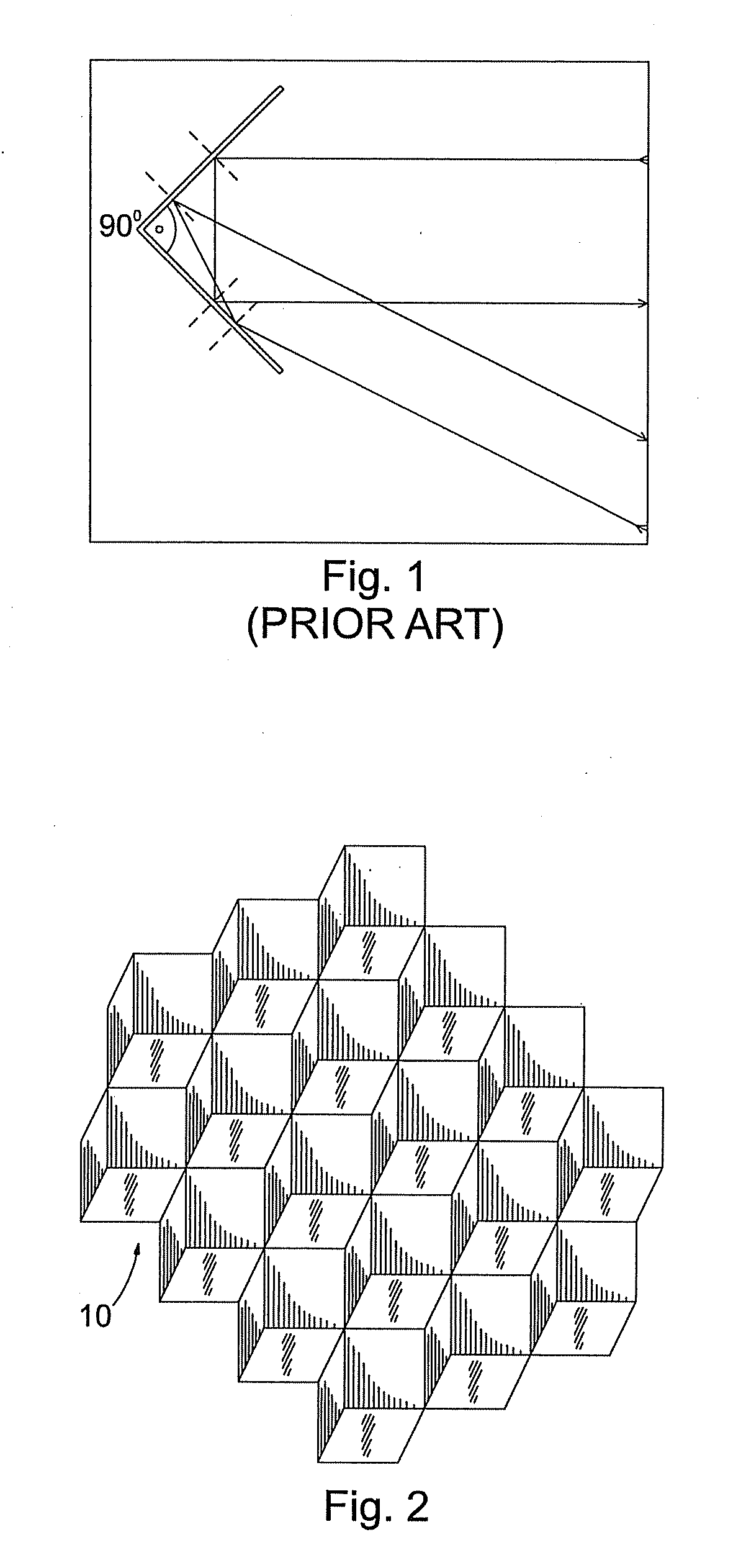
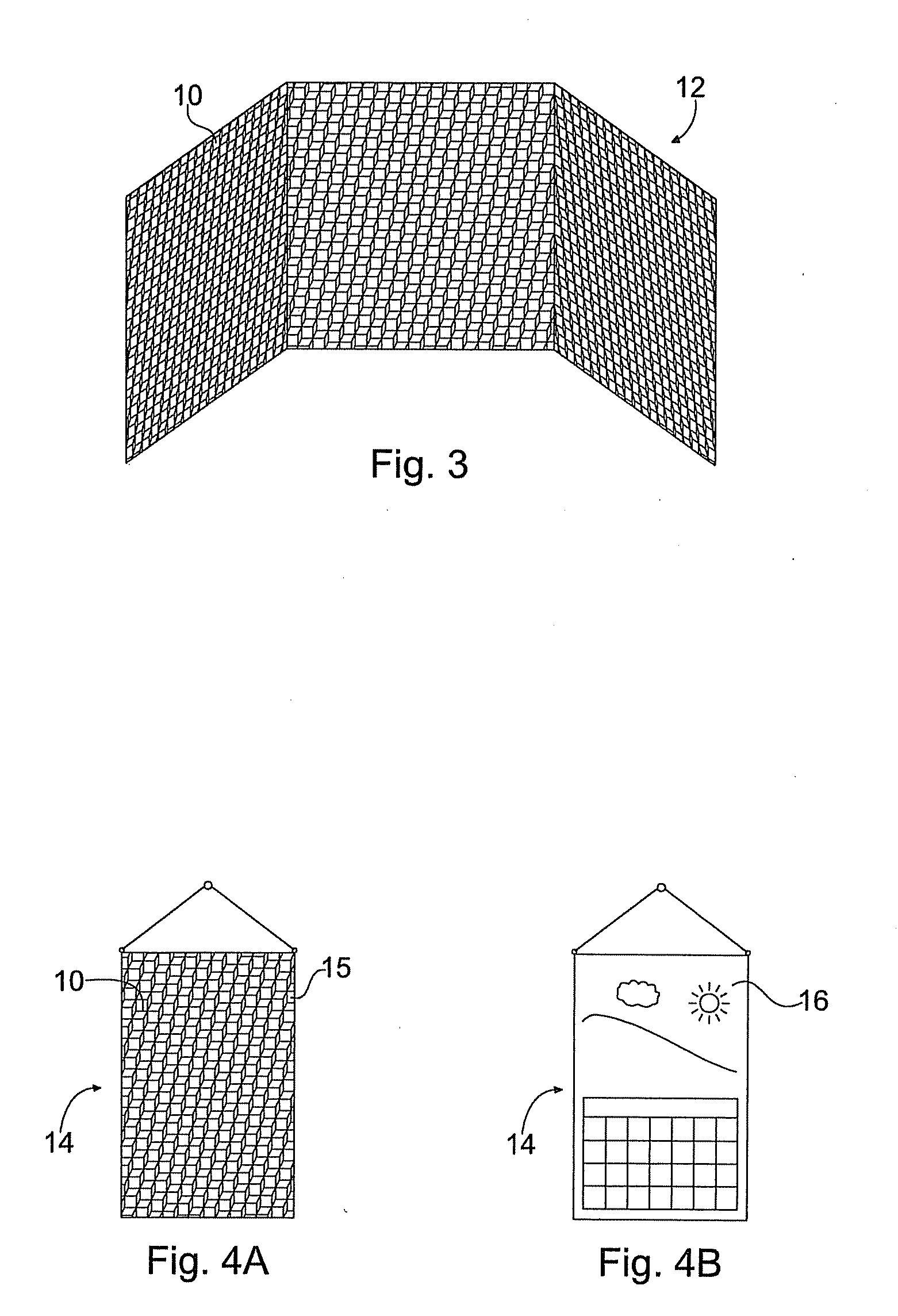
[0030]FIG. 1 depicts the working principles of a simple corner reflector. As is known in the art, a corner cube reflector includes three mutually perpendicular, intersecting flat surfaces, which reflect electromagnetic waves, including heat radiation, back to the source. In contrast, a flat reflector (e.g., mirror), causes heat reflected therefrom to bounce off at an angle of reflection equal to the angle of incidence, so heat will only return to the source from the portion of the flat reflector that is aligned perpendicularly to the source. One solution is to curve the reflective surface, which is adequate to the extent that the area to be kept warm is near the center of curvature of the curved reflective...


PUM


Abstract

A method for conserving heat emanated from an individual includes situating a corner reflector array near the individual, whereby the heat is retro-reflected back to the individual. The corner reflector array may include a plurality of corner cube reflectors. An apparatus for retro-reflecting heat back to the individual includes a plurality of corner cube reflectors arranged in an array and adapted to be mounted to a wall, ceiling, or other surface.

Description

CROSS REFERENCE TO RELATED APPLICATIONS[0001]This application claims the benefit of U.S. Provisional Patent Application No. 61 / 022,965 filed Jan. 23, 2008, and entitled “System and Method for Heat Energy Conservation Via Corner Reflectors,” the contents of which are incorporated herein by reference.BACKGROUND OF THE INVENTION[0002]1. Field of the Invention[0003]The present invention relates to the use of corner reflectors for heat conservation and, more particularly, to the use thereof in a living environment and other applications.[0004]2. Description of Related Art[0005]Generally, individuals prefer to be and feel warm in cool weather. Ideally, the indoor temperature would be increased to maintain a warm ambient temperature condition. However, there are usually significant energy costs associated with maintaining this desirable condition. To address these energy concerns, homes and businesses have lowered thermostat settings to save money and lower carbon dioxide emissions. Of cou...

Claims


Application Information

Patent Timeline
IPC IPC(8): G02B5/124
CPCG02B5/124
Inventor MYERS, BLAINE E.
Owner MYERS BLAINE E
Learn More