Method of decomposing constituents of a test sample and estimating fluorescence lifetime

a technology of constituents and test samples, applied in the field of optical imaging of biological tissue, can solve the problems of background signal interference, inability to completely eliminate background signal, and inability to decompose constituents of test samples

Inactive Publication Date: 2009-07-23
SOFTSCAN HEALTHCARE GROUP
View PDF1 Cites 17 Cited by
  • Summary
  • Abstract
  • Description
  • Claims
  • Application Information

AI Technical Summary

Problems solved by technology

A common issue encountered in practical application is interference from the background signal, which is the inherent signal detected by an imaging device when target fluorescent material is absent.
Various techniques can be employed to reduce the background signal, but it cannot be completely eliminated.
The intensity-based calibration of these indicators is difficult and prone to errors.
However, this can be computationally expensive and therefore not practical in many applications.

Method used


Image

  • Method of decomposing constituents of a test sample and estimating fluorescence lifetime
  • Method of decomposing constituents of a test sample and estimating fluorescence lifetime
  • Method of decomposing constituents of a test sample and estimating fluorescence lifetime

Examples


Embodiment Construction

Time-Domain Optical Imaging Apparatus

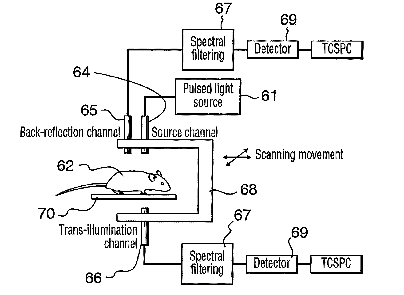
[0030]Shown in FIG. 1 is time-domain optical imaging apparatus that may be used with the method of the present invention. Systems such as this are known in the art, and other configurations may also make use of the invention. In the arrangement of FIG. 1, source 61 provides light. The light is directed towards a predetermined point of light injection on object 62 using source channel 64. The source channel 64 is an optical means for directing the light to the desired point on the object 62 and may include a fiber optic, reflective mirrors, lenses and the like. A first detector channel 65 is positioned to detect emission light in a back-reflection geometry and a second detector channel 66 is positioned in a trans-illumination geometry. The detector channels 65 and 66 are optical means for collecting the emission light from desired points on object 62 and are optically coupled to photon detector 69. As with the source channel 64, the detector chann...


PUM


Abstract

The present invention relates to a method of decomposition of a test sample into constituents thereof. The method proceeds by optically imaging the test sample to obtain a corresponding unknown time-domain resolved signal and decomposes the unknown time-domain resolved signal by comparing the unknown time-domain resolved signal with time-domain resolved reference signals. Furthermore, the method allows the determination of the presence or absence of constituents. Relative quantities may also be determined if sample material properties are known or taken into account. Lifetime decay of the constituents may also be estimated by handling effect of light diffusion in the test sample as time decay.

Description

FIELD OF THE INVENTION[0001]This invention relates generally to the field of optical imaging of biological tissue and, more specifically, to decomposing of constituents of a test sample and corresponding fluorescence lifetime.BACKGROUND OF THE INVENTION[0002]Recent advancement and increased commercial availability for small animal diffuse optical molecular imagers have provided significant benefits to the molecular biology community. The use of specific fluorescent markers (e.g., cyanine dyes, reporter genes such as green fluorescent protein (GFP) and mutated allelic forms such as yellow and red fluorescent protein (YFP, RFP)) enables in vivo studies of cellular and molecular processes. Among the advantages associated with optical imaging methods are the small numbers of animals required per study (because of the innocuous nature of the technology), the significant sensitivity and specificity, and the ease of combining fluorescent markers with specifically targeted probes.[0003]Fluo...

Claims


Application Information

Patent Timeline
Patent Type & Authority Applications(United States)
IPC IPC(8): G01J1/58
CPCA61B5/0059G01J3/4406G01N21/6408G01N21/6428A61B2503/40G01N2021/6419G01N2021/6441G01N2021/6484G01N21/6456
Inventor MA, GUOBINKHAYAT, MARIO
Owner SOFTSCAN HEALTHCARE GROUP
Why Eureka
Try Eureka