Eureka AIR delivers breakthrough ideas for toughest innovation challenges, trusted by R&D personnel around the world.

Intake air temperature (IAT) rationality diagnostic with an engine block heater

a rationality and engine technology, applied in the field of vehicle diagnostics, can solve the problems of skewed iat sensor/output, failure to report, and problem, however, in the art, and achieve the effect of preventing erroneous indications and reducing or eliminating false failures

Inactive Publication Date: 2009-07-16
DELPHI TECH INC
View PDF7 Cites 28 Cited by
  • Summary
  • Abstract
  • Description
  • Claims
  • Application Information

AI Technical Summary

Benefits of technology

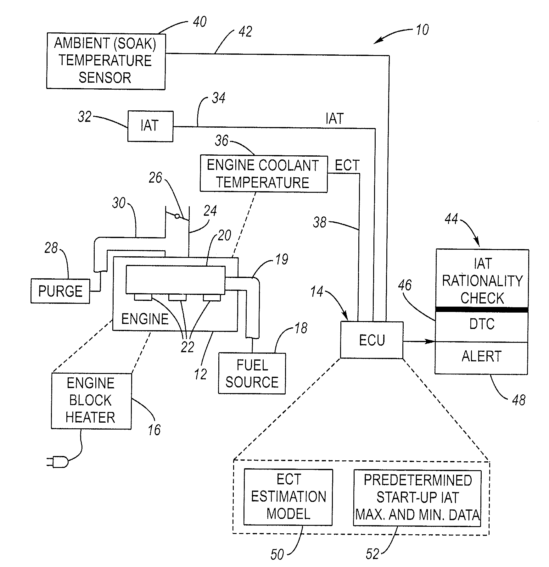
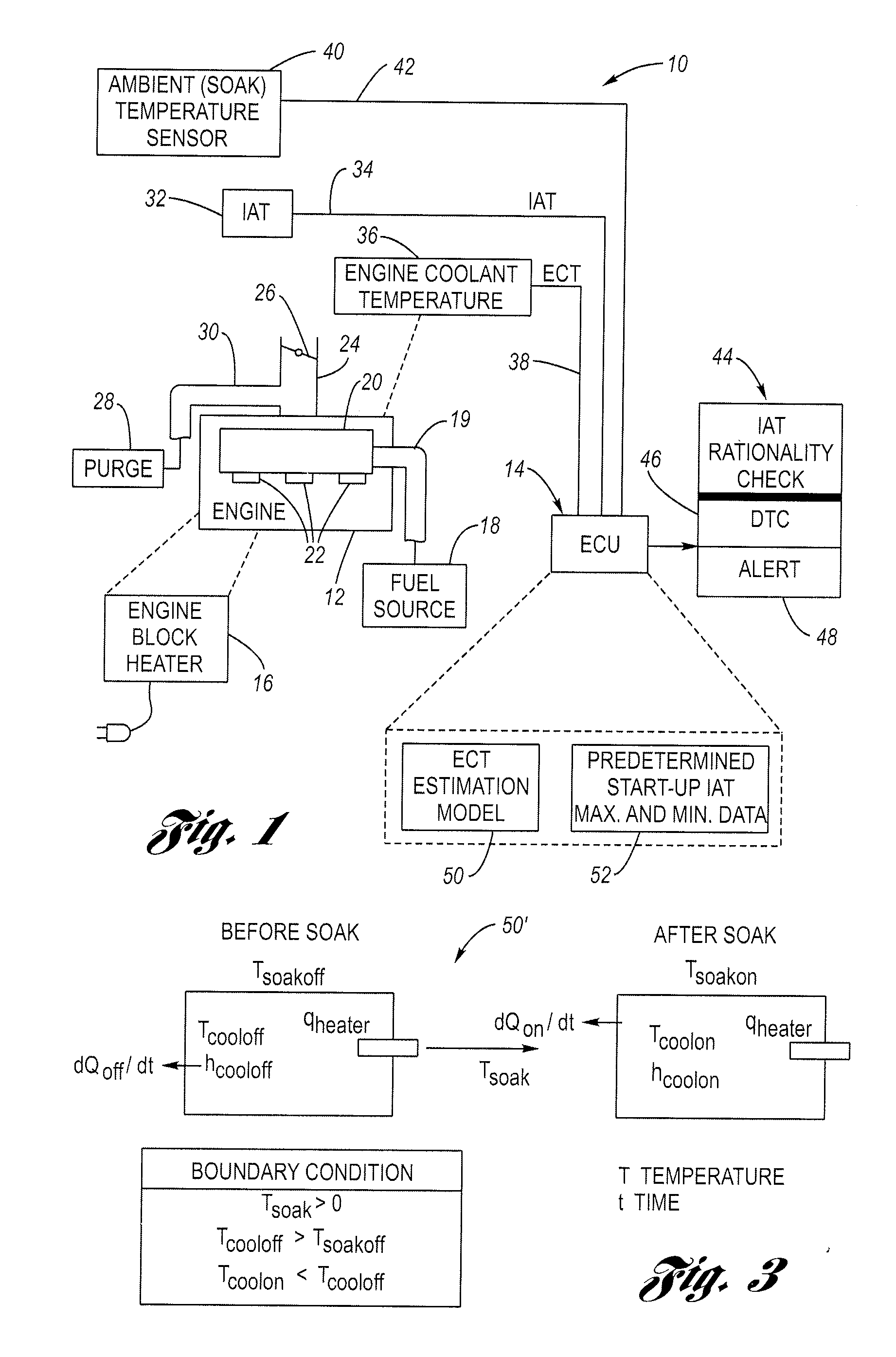
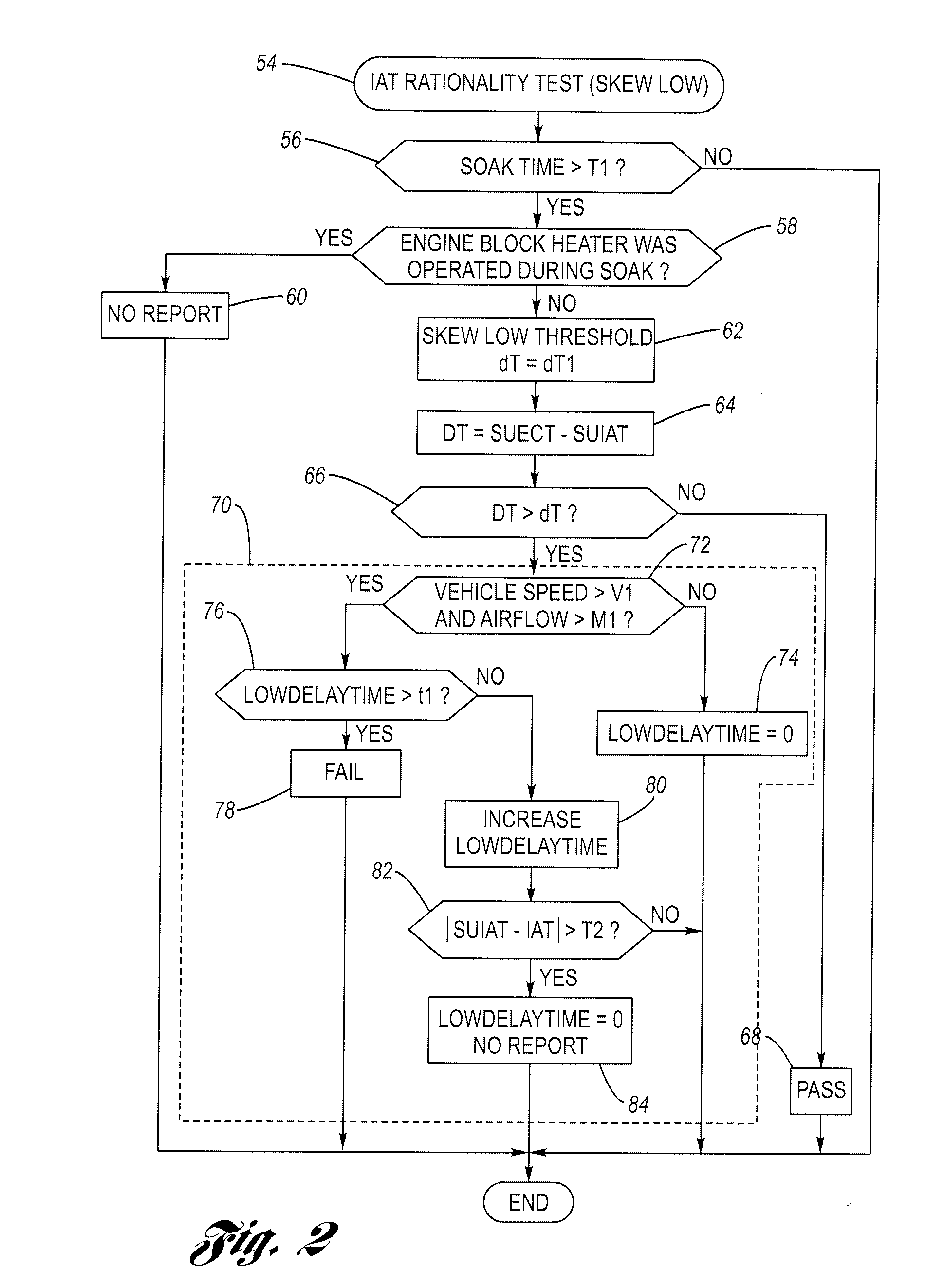
[0007]An advantage of one aspect of the invention (i.e., the engine block heater detection logic aspect) is that it provides a mechanism for detecting whether an engine block heater has been operated during the preceding soak period. This knowledge may be used to perform subsequent diagnostics, such as an IAT rationality (skew low) test or an ECT rationality (skew) test. Another advantage, in a second aspect of the invention (i.e., the particular use of the block heater detection logic in an IAT rationality test) is that it reduces or eliminates false failures that might otherwise occur. Various methods, performed during engine start-up, to discern if an engine block heater was operated during the previous cold weather soak are disclosed. If a diagnostic test (e.g., IAT skew) determines that the engine block heater was operated during soak, then the results of any such diagnostic will be ignored (e.g., not reported), preventing an erroneous indication that there is a rationality problem.

Problems solved by technology

If the subsequent IAT reading(s) do not show sufficient change within the predetermined time, the IAT rationality test will conclude that the IAT sensor / output is skewed and a failure will be reported.
However, if there is sufficient change in the IAT, no report is made, on the belief that unstable ambient conditions caused the initial skew between the start-up IAT and start-up ECT.
A problem, however, exists in the art.
Operation of the engine block heater, however, can confuse the IAT diagnostics logic described above.
The IAT rationality test described above, in the face of this data, concludes that there is a rationality problem with the IAT sensor output since it is skewed to the low side of the ECT.
This conclusion, however, is erroneous.
Moreover, since the engine block heater is operated from externally-provided AC power, it is not possible for an engine control unit (ECU) or the like to directly detect if an engine block heater was operated during soak.

Method used


Image

  • Intake air temperature (IAT) rationality diagnostic with an engine block heater
  • Intake air temperature (IAT) rationality diagnostic with an engine block heater
  • Intake air temperature (IAT) rationality diagnostic with an engine block heater

Examples


first embodiment

[0056]FIG. 5 is a flowchart showing, in greater detail, the step 58 of FIG. 2 (i.e., the step of determining whether the engine block heater was operated during the soak period). As described above, in the first embodiment, a thermal dynamic model is used, and is represented by the block 50 in FIG. 1 (accessible by the logic programmed in the ECU 14). The method begins in step 96.

[0057]In step 96, the ECU 14 determines whether the vehicle “ignition” is off. Ignition off is conventionally understood to mean that the operator of the vehicle has turned the ignition key to the off position. The ECU 14, in response, attends to a variety of matters before actually shutting down the engine, including items to be described in connection with this FIG. 5. If the answer in step 96 is YES, then the method proceeds to step 98.

[0058]In step 98, the ECU 14 is configured to read and store the ambient temperature Tsoakoff and the engine coolant temperature Tcooloff. These values, as described above...

second embodiment

[0066]Some vehicle models do not have an ambient (soak) temperature sensor 40, and use only the IAT sensor 32 for air flow calculations and the like. Accordingly the invention will be described in connection with FIGS. 6-7 that does not require an ambient (soak) temperature sensor / reading.

[0067]FIG. 6 is a chart showing start-up IAT data as a function of start-up ECT values, particularly illustrating minimum and maximum start-up IAT thresholds. Over a large number of cool-down tests, it was observed that the data collected defined a specific window in which IAT values indicate that the engine block heater 16 was operated during the soak period. This was evident even over different winds speeds (e.g., 0 mph and 30 mph air speeds were used). Such a window is bounded by a trace 120 corresponding to a minimum start-up IAT threshold and a trace 122 corresponding to a maximum start-up IAT threshold. The method will first use the measured start-up ECT to identify corresponding minimum and ...


PUM


Abstract

A first method is suitable for vehicles having an ambient temperature sensor and employs an estimation model configured to estimate a minimum start-up engine coolant temperature (SUECT) if the engine block heater was operated during the previous soak period. A measured SUECT is then compared to estimated minimum SUECT from the model, and if it is higher, then the diagnostic logic concludes that the engine block heater was operated during the soak period, and disables the reporting its test results. A second method is suitable for vehicles without an ambient (soak) temperature sensor employs an alternative approach. Predetermined data based on actual vehicle testing over a wide range of conditions is stored in a data structure. The data describe respective minimum and maximum start-up IAT thresholds versus SUECT. The thresholds are spaced apart to define a start-up IAT window in between. In other words, the window is bounded by minimum and maximum start-up IAT thresholds. For any measured SUECT, a particular window will be set. If the measured start-up IAT falls within the window, then the engine block heater was operated during the soak period.

Description

TECHNICAL FIELD[0001]The invention relates generally to vehicle diagnostics and more particularly to a method of checking the rationality of an intake air temperature (IAT) reading for engine configurations having an engine block heater.BACKGROUND OF THE INVENTION[0002]Increasing awareness of the effects of vehicle exhaust emissions and the like has resulted in regulations to control these emissions. In particular, various federal and state on-board diagnostic regulations (e.g., OBDII) require that certain emission related systems on the vehicle be monitored, and that a vehicle operator be notified if the system is not functioning in a predetermined manner. Automotive vehicle electronics therefore include a programmed diagnostic data manager or the like service configured to receive reports from diagnostic algorithms / circuits concerning the operational status of various components or systems and to set / reset various standardized diagnostic trouble codes (DTC) and / or otherwise genera...

Claims


Application Information

Patent Timeline
IPC IPC(8): F02D35/00
CPCF01P2025/32F01P2031/30F02D41/062F02N19/10F02D2041/1433F02D2200/0414F02D2400/08F02D41/22
Inventor YANG, KOON CHULSHEFFER, TIMOTHY K.
Owner DELPHI TECH INC
Why Eureka
Eureka Blog
Learn More