Digital Video Decoder Architecture

a video decoder and architecture technology, applied in the direction of color television details, color signal processing circuits, electrical apparatus, etc., can solve the problems of gaussian-like noise in analog video transferred over transmission lines, tv signals may introduce gaussian-like noise,

Active Publication Date: 2009-07-16
ZHANGJIAGANG KANGDE XIN OPTRONICS MATERIAL
View PDF13 Cites 20 Cited by
  • Summary
  • Abstract
  • Description
  • Claims
  • Application Information

AI Technical Summary

Problems solved by technology

Due to advancing semiconductor processing technology, integrated circuits (ICs) have greatly increased in functionality and complexity.
For example, modulation, wireless transmission and demodulation of TV signals may introduce Gaussian-like noise.
Furthermore, even analog video transferred over transmission lines may have Gaussian-like noise due to magnetic fields around the transmission lines.
In addition, the digitalizing process may inadvertently amplify minor noise problems in the analog video stream.
Imperfect decoding of composite video signals in either PAL or NTSC format may lead to color-crossing.
Specifically, color-crossing error often appears in a video image where the local luminance spatial frequency is near the sub-carrier frequency of the chrominance information.
Color-crossing errors occur in both PAL and NTSC video signals.
Thus, the luminance components near the chrominance sub-carrier frequency cause color-crossing errors, which cannot be cleanly removed.
Color-crossing error can also occur in other encoded video signals.
While 3D comb filters can reduce color-crossing errors, 3D comb filters may also degrade other aspects of video quality.
For example, 3D comb filters are very sensitive to noise in composite video signals; therefore, a digital video decoder with a 3D comb filter would have difficulties with weak video signals, which are common in many areas.
Furthermore, high quality 3D comb filters are very expensive relative to other components of a video system.

Method used


Image

  • Digital Video Decoder Architecture
  • Digital Video Decoder Architecture
  • Digital Video Decoder Architecture

Examples


Embodiment Construction

[0046]In the following description, reference is made to the accompanying drawings which illustrate several embodiments of the present invention. It is understood that other embodiments may be utilized and mechanical, compositional, structural, electrical, and operational changes may be made without departing from the spirit and scope of the present disclosure. The following detailed description is not to be taken in a limiting sense. Furthermore, some portions of the detailed description which follows are presented in terms of procedures, steps, logic blocks, processing, and other symbolic representations of operations on data bits that can be performed in electronic circuitry or on computer memory. A procedure, computer executed step, logic block, process, etc., are here conceived to be a self-consistent sequence of steps or instructions leading to a desired result. The steps are those utilizing physical manipulations of physical quantities. These quantities can take the form of e...


PUM


Abstract

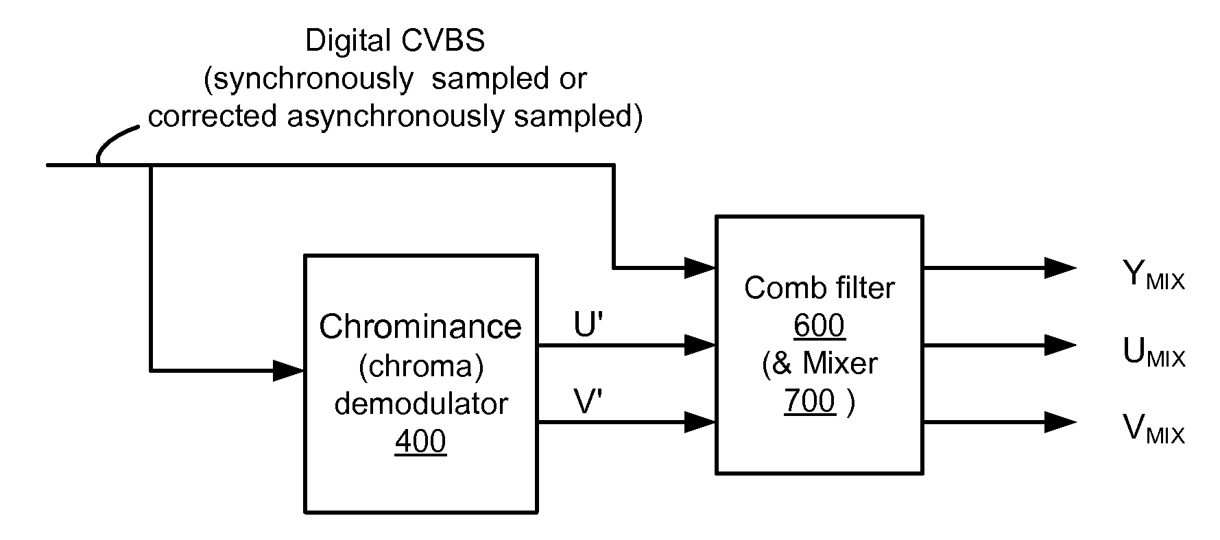
A digital video decoder architecture is provided wherein chrominance values are determined first, then luminance values are determined, in part, based on the previously determined chrominance values. In this architecture, luminance separation occurs after and based on

Description

CROSS-REFERENCE TO RELATED APPLICATIONS[0001]This application claims the benefit under 35 U.S.C. 119(e) of U.S. Provisional Application Ser. No. 61 / 020,718, filed Jan. 12, 2008, which is incorporated herein by reference.BACKGROUND OF THE INVENTION[0002]1. Field of the Invention[0003]The invention relates to digital video decoders and in particular to a digital video decoder architecture producing a luminance value based on one or more chrominance values.[0004]2. Background of the Invention[0005]Due to advancing semiconductor processing technology, integrated circuits (ICs) have greatly increased in functionality and complexity. With increasing processing and memory capabilities, many formerly analog tasks are being performed digitally. For example, images, audio and full motion video can now be produced, distributed, and used in digital formats.[0006]Although digital images generally provide higher noise immunity, most digital images in digital video streams are converted from analo...

Claims


Application Information

Patent Timeline
IPC IPC(8): H04N9/66
CPCH04N9/66H04N9/646H04N9/78H04N9/72
Inventor JANG, SHENG DEWONG, HSIU MINXIAO, PENG
Owner ZHANGJIAGANG KANGDE XIN OPTRONICS MATERIAL
Why Eureka
Try Eureka