
Hollow curved superelastic medical needle and method

a superelastic, medical needle technology, applied in the field of medical devices, can solve the problems of affecting the accuracy of the needle, the inability of single infusion to fill the entire target area, and the complicated medical procedures involving the vertebra

Inactive Publication Date: 2009-07-09
COOK INC
View PDF42 Cites 23 Cited by
  • Summary
  • Abstract
  • Description
  • Claims
  • Application Information

AI Technical Summary

Benefits of technology

"The patent describes an infusion needle made of a rigid superelastic material that can be bent and straightened repeatedly. The needle has a preformed bend along its length, which allows it to deflect laterally and rotate to reach multiple planes in the body. This makes it easier to access target sites and reduces the need for multiple needle sticks. The needle can be heated or cold worked to create its desired shape, and it can be used with a trocar or stylet to facilitate access to tissue. The needle can also be used in vertebroplasty procedures to infuse stabilizing cement with a single access of the vertebral body. Overall, the patent provides a solution for creating an infusion needle with improved flexibility and access capabilities."

Problems solved by technology

Medical procedures involving the vertebrae are typically complicated because of the preciseness required to avoid both neural damage and injury to major blood vessels, as well as the indirect path that is usually required to access the treatment site.
A single infusion usually cannot fill the entire target area because the needle tip cannot be redirected from the original plane of entry.
Continued infusion of cement from the first access site will usually not result in an adequate infusion due to the tendency of the material to set before it fills all of the affected area, thereby becoming a baffle to itself.
Furthermore, the thick density of the marrow and structures, such as veins, usually acts to impede free flow of the cement within the vertebral body.
Another concern during the procedure is accidental puncture of the these veins.
Because vertebral veins lead directly to the lungs, there is a significant risk of pulmonary embolism if cement is accidentally introduced therein.
The inability to adequately maneuver the needle cannula tip within a body or around structures is a major limitation of the straight needle.
Additional needle sticks to complete a medical procedure result in discomfort to the patient and additional risk of leakage and other complications.
Rigid curved needles are well known for suturing applications; however, adding anything more than a slight bend to an infusion needle limits its access path and ability to deeply penetrate tissue, especially bone.
For example, a rigid curved needle is unsuitable for use in a vertebroplasty procedure where the needle cannula must be driven through the bone and deep into the vertebral body using a relatively straight approach and maintained in place to avoid additional damage to the entry site.
Accomplishing this is problematic.
While stainless steel needles having a slight distal bend are known, the amount of needle curvature necessary to provide adequate lateral infusion is not possible—the needle plasticly deforms once inside the outer restraining cannula and hence is unable to return resiliently to its preformed shape.
Other medical procedures present similar problems when a single straight needle is used.
The problem is that the infusion may not penetrate any deeper than the needle tract; thus portions of the tumor are not effectively treated.

Method used


Image

  • Hollow curved superelastic medical needle and method
  • Hollow curved superelastic medical needle and method
  • Hollow curved superelastic medical needle and method

Examples


Embodiment Construction

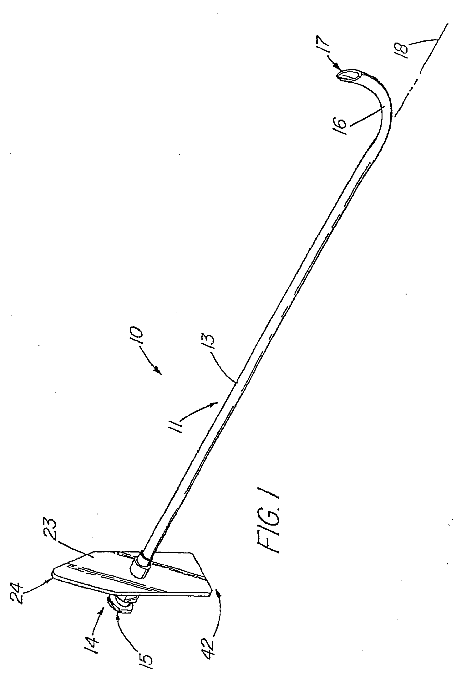
[0058]FIG. 1 depicts a needle assembly 10 comprising an infusion needle 11 with a preformed bend 16 for lateral infusion or aspiration of medicaments and other materials. As defined herein, the “needle assembly 10” can comprise infusion needle 11 alone or infusion needle 11 in combination with other components. The “infusion needle 11” as defined herein comprises one or more needle cannulae having a preformed bend 16.

[0059]The infusion needle 11 of FIG. 1 is comprised of a superelastic alloy needle cannula 13, preferably the alloy sold under the trademark Nitinol, that is soldered or otherwise affixed to a well-known needle hub 14 using one of a selected number of well-known techniques, including that of Hall described in U.S. Pat. No. 5,354,623 whose disclosure is expressly incorporated herein by reference, and a flange 23 which has a first tapered or pointed end 24 whose shape is readily distinguishable from the second, squared end 42.

[0060]First end 24 corresponds to the directio...


PUM


Abstract

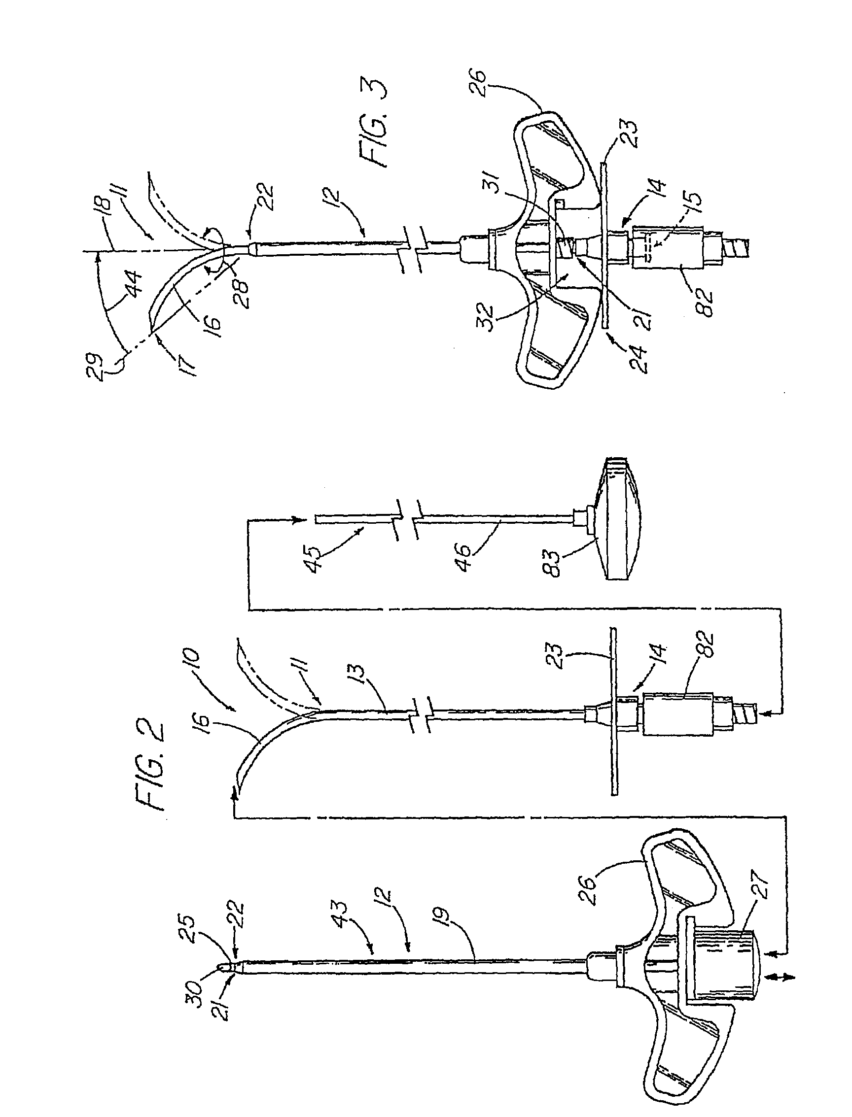
A needle assembly 10 compromising an infusion needle 11 that includes a needle cannula 13 made of a superelastic material such as Nitinol. The needle cannula is cold-worked or heat annealed to produce a preformed bend 16 that can be straightened within passageway 21 of a coaxial outer cannula 12 for introduction into the body of a patient. Upon deployment from the outer cannula, the needle cannula substantially returns to the preformed configuration for the introduction or extraction of materials at areas lateral to the entry path of the needle assembly. The needle assembly can compromise a plurality of needle cannulae than can be variably arranged or configured for attaining a desired infusion pattern.

Description

CROSS-REFERENCE TO RELATED APPLICATIONS[0001]This application is a continuation of U.S. patent application Ser. No. 11 / 281 / 151, filed Nov. 17, 2005, which is a continuation of U.S. patent application Ser. No. 10 / 678,774, filed Oct. 3, 2003, now abandoned, which is a continuation of U.S. patent application Ser. No. 10 / 201,112, filed Jul. 22, 2002, now abandoned, which is a continuation of U.S. patent application Ser. No. 09 / 668,067, filed Sep. 22, 2000, now U.S. Pat. No. 6,425,887 issued Jul. 30, 2002, which is a divisional of U.S. patent application Ser. No. 09 / 457,844, filed on Dec. 9, 1999, now U.S. Pat. No. 6,592,559 issued Jul. 15, 2003, which claims the benefit of U.S. Provisional Patent Application Ser. Nos. 60 / 111,624, filed Dec. 9, 1998 and 60 / 130,597 filed Apr. 22, 1999, each of which is hereby incorporated herein by reference.TECHNICAL FIELD[0002]This invention relates generally to medical devices and more particularly to needles that are curved for indirect infusion acces...

Claims


Application Information

Patent Timeline
Patent Type & Authority Applications(United States)
IPC IPC(8): A61M5/32A61M5/158A61B17/00A61B17/34A61M25/00A61M25/06
CPCA61B17/3417A61B17/3468A61B17/3478A61B2017/00261A61B2017/00867A61B17/1671A61M25/0043A61M25/06A61M25/0606A61M2025/0007A61M2205/0266A61M25/0041
Inventor MCGUCKIN, JR., JAMES F.PAKTER, ROBERT L.MORRIS, EDWARD J.
Owner COOK INC
Learn More