Eureka AIR delivers breakthrough ideas for toughest innovation challenges, trusted by R&D personnel around the world.

Cryogenic cooling of mri/nmr coils using integrated microfluidic channels

a technology of microfluidic channels and mri/nmr coils, which is applied in the direction of superconducting magnets/coils, magnetic bodies, instruments, etc., to achieve the effect of maintaining subject comfort and improving coil efficiency

Inactive Publication Date: 2009-07-09
TEXAS A&M UNIVERSITY
View PDF4 Cites 22 Cited by
  • Summary
  • Abstract
  • Description
  • Claims
  • Application Information

AI Technical Summary

Benefits of technology

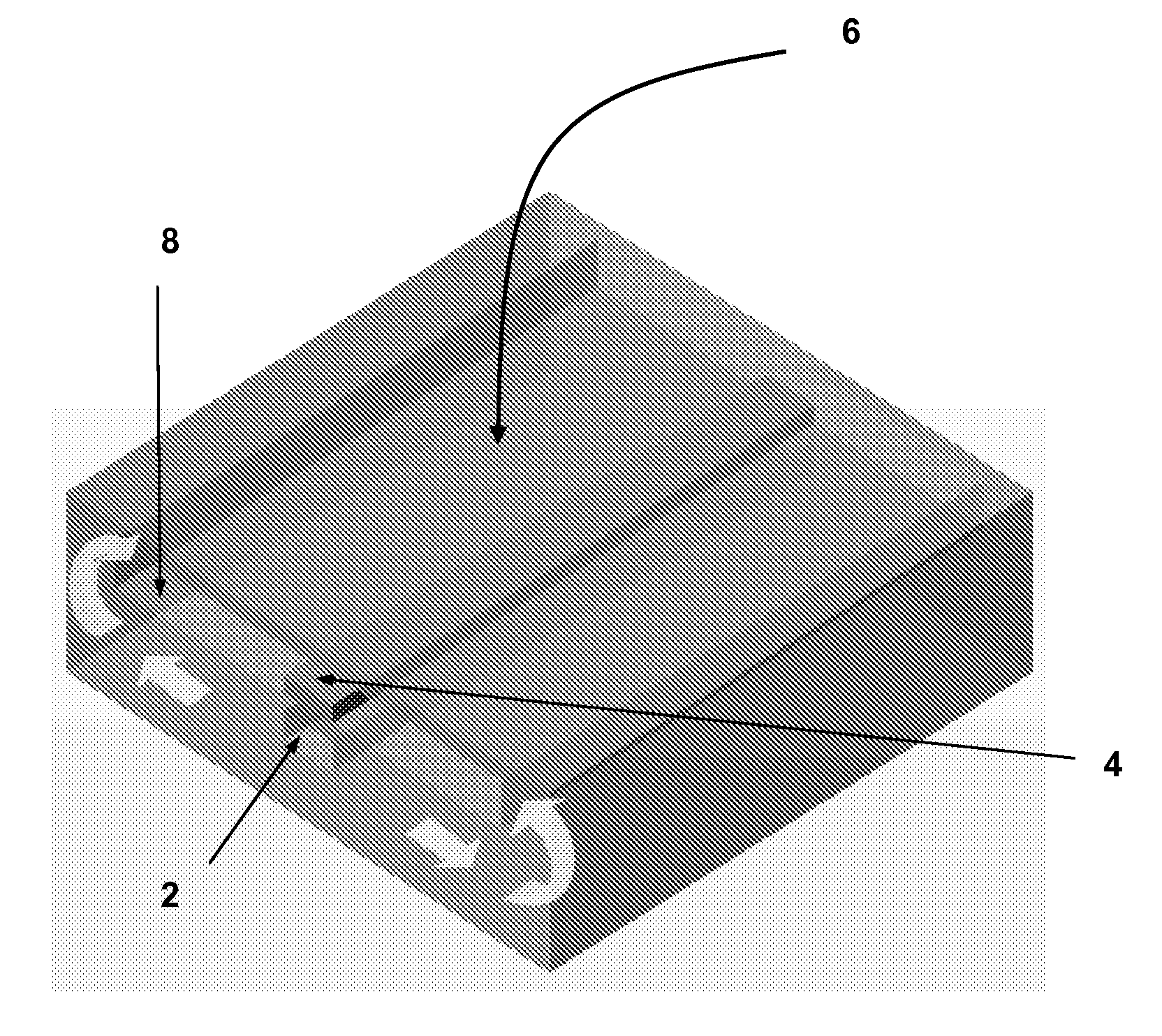
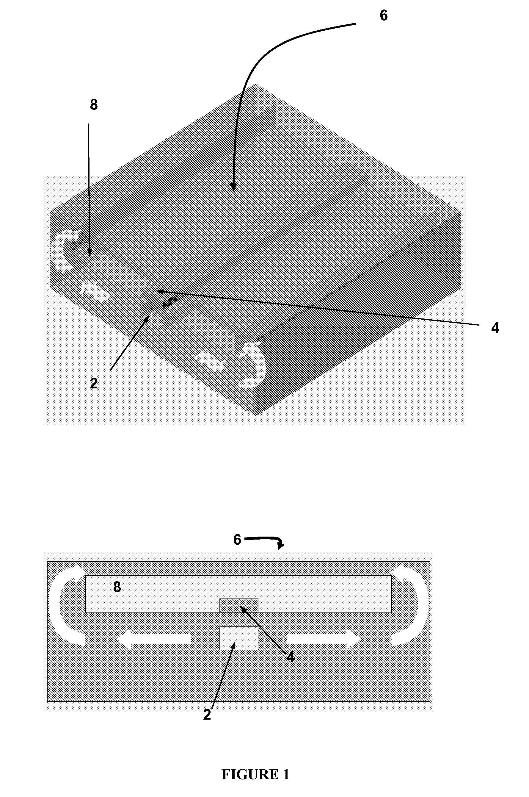
[0010]The present invention is an assembly with a magnet (or coil) for magnetic resonance imaging having a substrate with an imaging surface and an opening within the substrate adjacent the imaging surface. In conventional MRI, the coils do not generate any heat, not like electronic equipments, mainly because the power used is very small, therefore, conventional coils run at room temperature. The present invention provides for cooling of the resonance source to improve the efficiency of coils, while maintaining subject comfort. The system has a magnetic resonance coil within the opening and opposite the imaging surface with a cryo-cooling via disposed within the substrate and below the magnetic resonance coil. Opposite the imaging surface, the via has an inlet and an outlet for a cryogenic fluid, wherein the cryogenic fluid cools the radiofrequency coil and the opening buffers the tissue target at or about the imaging surface from the small heat capacity of microscale cryogenic fluid channel directly cooling the radiofrequency coil. In one embodiment, the cryogenic fluid cools the radiofrequency coil but not the imaging surface.

Problems solved by technology

In conventional MRI, the coils do not generate any heat, not like electronic equipments, mainly because the power used is very small, therefore, conventional coils run at room temperature.

Method used


Image

  • Cryogenic cooling of mri/nmr coils using integrated microfluidic channels
  • Cryogenic cooling of mri/nmr coils using integrated microfluidic channels
  • Cryogenic cooling of mri/nmr coils using integrated microfluidic channels

Examples


Embodiment Construction

[0036]While the making and using of various embodiments of the present invention are discussed in detail below, it should be appreciated that the present invention provides many applicable inventive concepts that can be embodied in a wide variety of specific contexts. The specific embodiments discussed herein are merely illustrative of specific ways to make and use the invention and do not delimit the scope of the invention.

[0037]To facilitate the understanding of this invention, a number of terms are defined below. Terms defined herein have meanings as commonly understood by a person of ordinary skill in the areas relevant to the present invention. Terms such as “a”, “an” and “the” are not intended to refer to only a singular entity, but include the general class of which a specific example may be used for illustration. The terminology herein is used to describe specific embodiments of the invention, but their usage does not delimit the invention, except as outlined in the claims.

[...


PUM

PropertyMeasurementUnit
diameteraaaaaaaaaa
temperatureaaaaaaaaaa
heat capacityaaaaaaaaaa

Abstract

The present invention includes an assembly with a magnet for magnetic resonance having a substrate with an imaging surface and an opening within the substrate adjacent the imaging surface. The present invention enhances the sensitivity and reduces the acquisition time of magnetic resonance imaging (MRI) and nuclear magnetic resonance (NMR) spectroscopy by cooling the coil using microfluidic channels through which a cryogenic fluid is pumped. Various embodiments have been detailed for clinical imaging or detection in which the integrated coil / microfluidic cryo-cooling system is outside the patient body or in vivo imaging or detection in which the integrated coil / microfluidic cryo-cooling system is inside the patient.

Description

CROSS-REFERENCE TO RELATED APPLICATIONS[0001]This application claims priority to U.S. Provisional Application Ser. No. 61 / 019,452, filed Jan. 7, 2008, the entire contents of which are incorporated herein by reference.TECHNICAL FIELD OF THE INVENTION[0002]The present invention relates in general to the field of thermal cooling of magnetic resonance imaging (MRI) / nuclear magnetic resonance (NMR) microcoils.STATEMENT OF FEDERALLY FUNDED RESEARCH[0003]None.BACKGROUND OF THE INVENTION[0004]Without limiting the scope of the invention, its background is described in connection with an apparatus and method for accomplishing heat transfer of magnetic resonance imaging / nuclear magnetic resonance (MRI / NMR) coils using microfluidic channels.[0005]The use of liquid nitrogen or liquid helium to cool the coil has been previously suggested in MRI and NMR. Recently, the idea of using microfluidic channels for cooling has been developed, mostly for electronic component cooling.[0006]For example, in U...

Claims


Application Information

Patent Timeline
Patent Type & Authority Applications(United States)
IPC IPC(8): G01V3/00H01F7/00
CPCG01R33/287G01R33/34007H01F6/04G01R33/34084G01R33/3415G01R33/3403
Inventor HAN, ARUMWRIGHT, STEVEN M.
Owner TEXAS A&M UNIVERSITY
Why Eureka
Eureka Blog
Learn More