
Outboard motor

a technology for outboard motors and motors, applied in the direction of marine propulsion, vessel construction, propulsive elements, etc., can solve the problems of increased cost, increased resistance to water, increased cost, etc., and achieve the effect of preventing an increase in water resistance and reducing cos

Active Publication Date: 2009-07-02
YAMAHA MOTOR CO LTD
View PDF7 Cites 1 Cited by
  • Summary
  • Abstract
  • Description
  • Claims
  • Application Information

AI Technical Summary

Benefits of technology

[0008]In view of the foregoing circumstances, preferred embodiments of the present invention provide an outboard motor in which configurations of connection portions of an upper casing with other members remain unchanged from those before a transmission is provided in the upper casing and in which the same members as those before the installation of the transmission can be used except for the upper casing, so that it is possible to minimize the cost related to the installation of the transmission and to prevent an increase in resistance to water.
[0013]The upper casing is preferably defined by the upper-side casing and the lower-side casing, and the mating surface between the upper-side casing and the lower-side casing is preferably laterally wider than the upper section and the lower section of the upper casing. Accordingly, the configuration of the upper casing can correspond to that of the transmission by widening only a portion in which the transmission is disposed while portions joined to other members such as the mounting plate and the lower casing remain unchanged. Therefore, various types of transmissions can be installed in the outboard motor without replacing members such as the mounting plate and the lower casing but by simply replacing the upper casing. Consequently, it is possible to greatly reduce and minimize the cost for installation of the transmission in the outboard motor.
[0014]In addition, since there is no need to extend a lateral width from the lower section of the upper casing through the lower casing, it is possible to prevent an increase in resistance to water.
[0015]The width between the upper mounts, which are provided as a right and left pair to mount the outboard motor to a hull, preferably is narrower than the lateral width of the mating surface portion in the upper casing. Therefore, it is possible to damp and prevent vibration of the hull by absorbing rotational vibrations of the outboard motor.
[0016]A divider arranged to divide the inside of the upper casing into a front chamber and a rear chamber is preferably provided by joining a divider of an upper-side casing and a divider of a lower-side casing, and the transmission is disposed in the front chamber. Thus, the transmission can easily be located in a desired position in the upper casing and can be prevented from being influenced or affected by components disposed in the rear chamber (heat, oil content, and moisture, for example).
[0017]A bolt seat for joining is preferably provided in the mating surface portion of the divider, and the mating surface of the divider is sealed. Thus, an upper-side and a lower-side divider can be rigidly joined together by bolting the mating surfaces of the dividers. It is also possible to completely separate the front chamber, which contains the transmission therein, from the rear chamber in which an exhaust pipe and the like are disposed. Accordingly, the transmission can further be prevented from being influenced or affected by the components disposed in the rear chamber (heat, oil content, and moisture, for example).

Problems solved by technology

It often happens that the upper casing in which the drive shaft is inserted does not have enough width to allow for the insertion of the transmission.
This causes a problem of increased cost.
Furthermore, when the lateral width is widened from a lower section of the upper casing through the lower casing for the insertion of the transmission in the upper casing, there arises a problem of increased resistance to water.

Method used


Image

  • Outboard motor
  • Outboard motor
  • Outboard motor

Examples


Embodiment Construction

[0025]Description will hereinafter be made of preferred embodiments of the present invention.

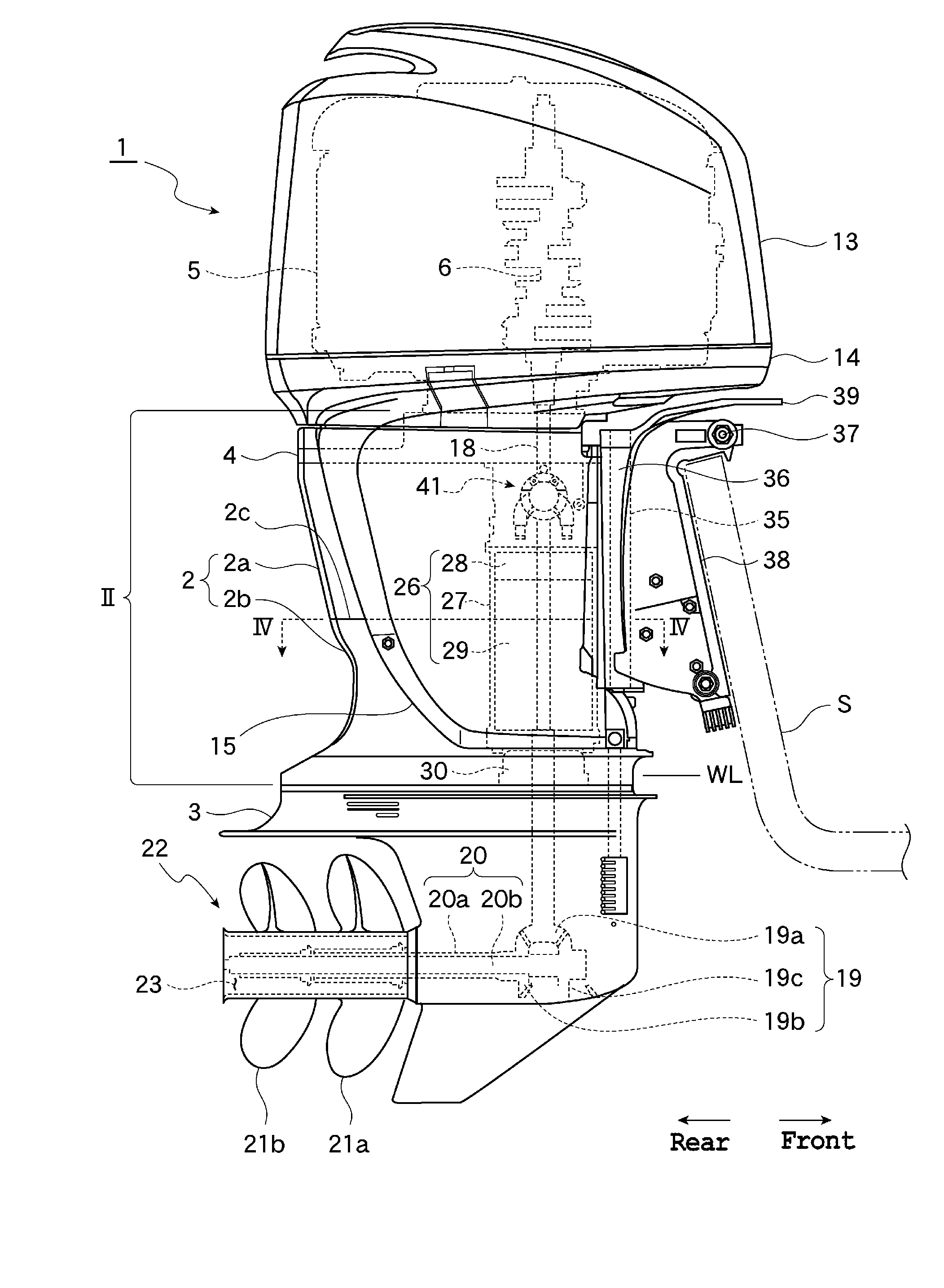
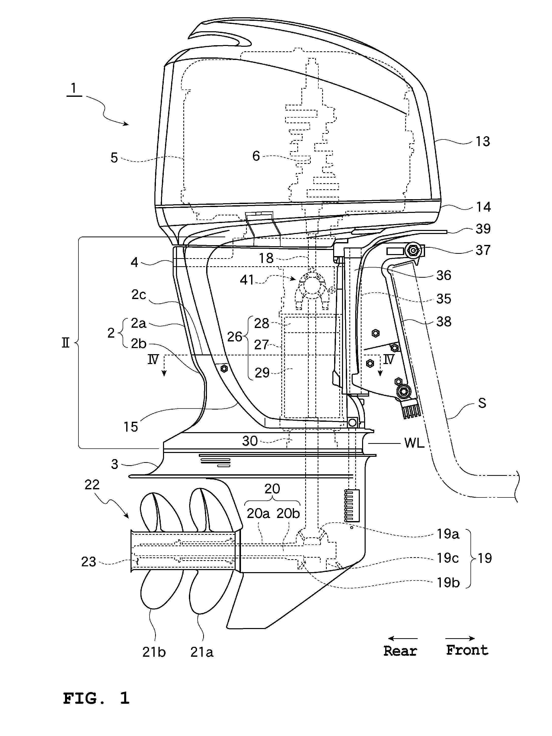
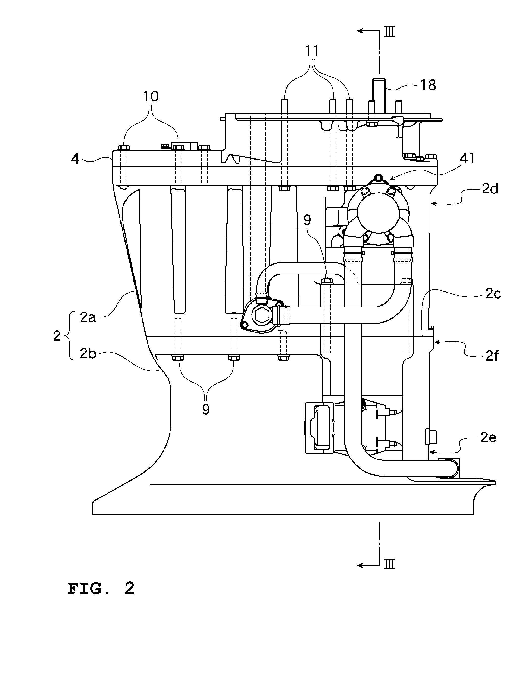
[0026]FIG. 1 is a right side view showing an outboard motor according to a preferred embodiment of the present invention. FIG. 2 is an enlarged view of a section II of FIG. 1 according to a preferred embodiment of the present invention. FIG. 3 is a longitudinal sectional view taken along the line III-III in FIG. 2 according to a preferred embodiment of the present invention. FIG. 4 is a transverse sectional view taken along the line IV-IV in FIG. 1 according to a preferred embodiment of the present invention. FIG. 5 is an exploded perspective view showing an upper casing and its surrounding members of the outboard motor according to a preferred embodiment of the present invention. FIG. 6 is a front view showing the upper casing of the outboard motor according to a preferred embodiment of the present invention. Here, FIG. 2 shows a state that a side cover 15, which will be described below, is...


PUM


Abstract

In an outboard motor, a lower casing is located below an upper casing, and an engine with a vertically-arranged crankshaft is mounted above the upper casing. The rotation of the crankshaft is transmitted to a drive shaft pivotally supported in the upper casing, has its speed changed by a transmission mounted on the drive shaft, and is transmitted to a propeller shaft pivotally supported in the lower casing. The upper casing includes an upper-side casing and a lower-side casing, and mating surface portions of the upper-side casing and the lower-side casing are laterally wider than an upper section and a lower section of the upper casing.

Description

BACKGROUND OF THE INVENTION[0001]1. Field of the Invention[0002]The present invention relates to an outboard motor having a mechanism arranged to transmit engine power to a propeller through a shaft, and especially relates to an outboard motor equipped with a transmission arranged to change the rotational speed of a shaft.[0003]2. Description of the Related Art[0004]Conventionally, in an outboard motor, engine power is transmitted to a crankshaft, a drive shaft, and a propeller shaft, and then is transmitted to a propeller from the propeller shaft. Conventionally, the engine power is transmitted as is to the propeller through each of the aforementioned shafts. Thus, when it is desired to change the speed of a watercraft, the engine power is adjusted to change the rotational speed of each shaft, so that the rotational speed of the propeller is changed subsequently to cause a change in the speed of the watercraft.[0005]However, recent outboard motors have been provided with a transmis...

Claims


Application Information

Patent Timeline
IPC IPC(8): B63H20/32
CPCB63H20/02B63H20/32B63H20/22B63H20/20
Inventor FUKUOKA, YOSHIHITO
Owner YAMAHA MOTOR CO LTD
Learn More