Connector connection terminals

a technology of connecting terminals and connecting terminals, which is applied in the direction of coupling device connections, printed circuits, coupling device details, etc., can solve the problems of easy plastic deformation and troublesome cutting tasks, and achieve the effects of convenient positioning with respect to the housing, enhanced assembly accuracy, and improved accuracy

Inactive Publication Date: 2009-07-02
DAIICHI SEIKO CO LTD
View PDF2 Cites 3 Cited by
  • Summary
  • Abstract
  • Description
  • Claims
  • Application Information

AI Technical Summary

Benefits of technology

[0012]According to the embodiment, the positioning with respect to the housin

Problems solved by technology

However, when cutting the connecting portion with the carrier, the connecting portion of the carrier is folded and cut, and

Method used


Image

  • Connector connection terminals
  • Connector connection terminals
  • Connector connection terminals

Examples


Embodiment Construction

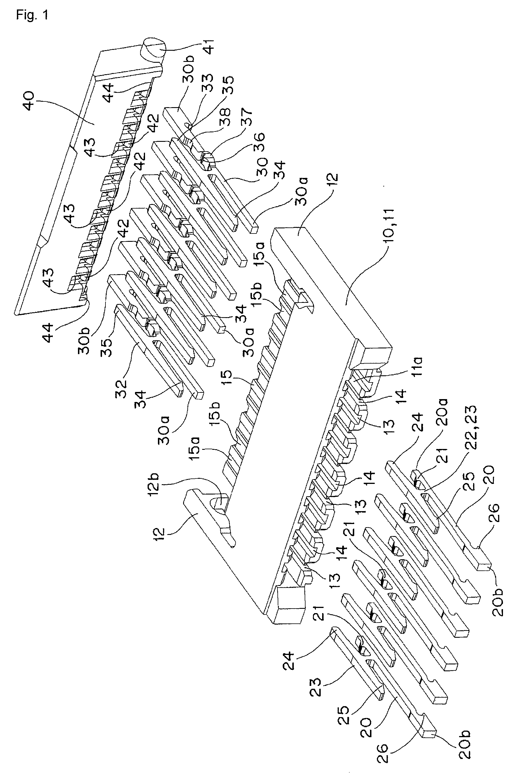
[0025]An embodiment of the present invention will be described according to the accompanied drawings of FIGS. 1 to 12.

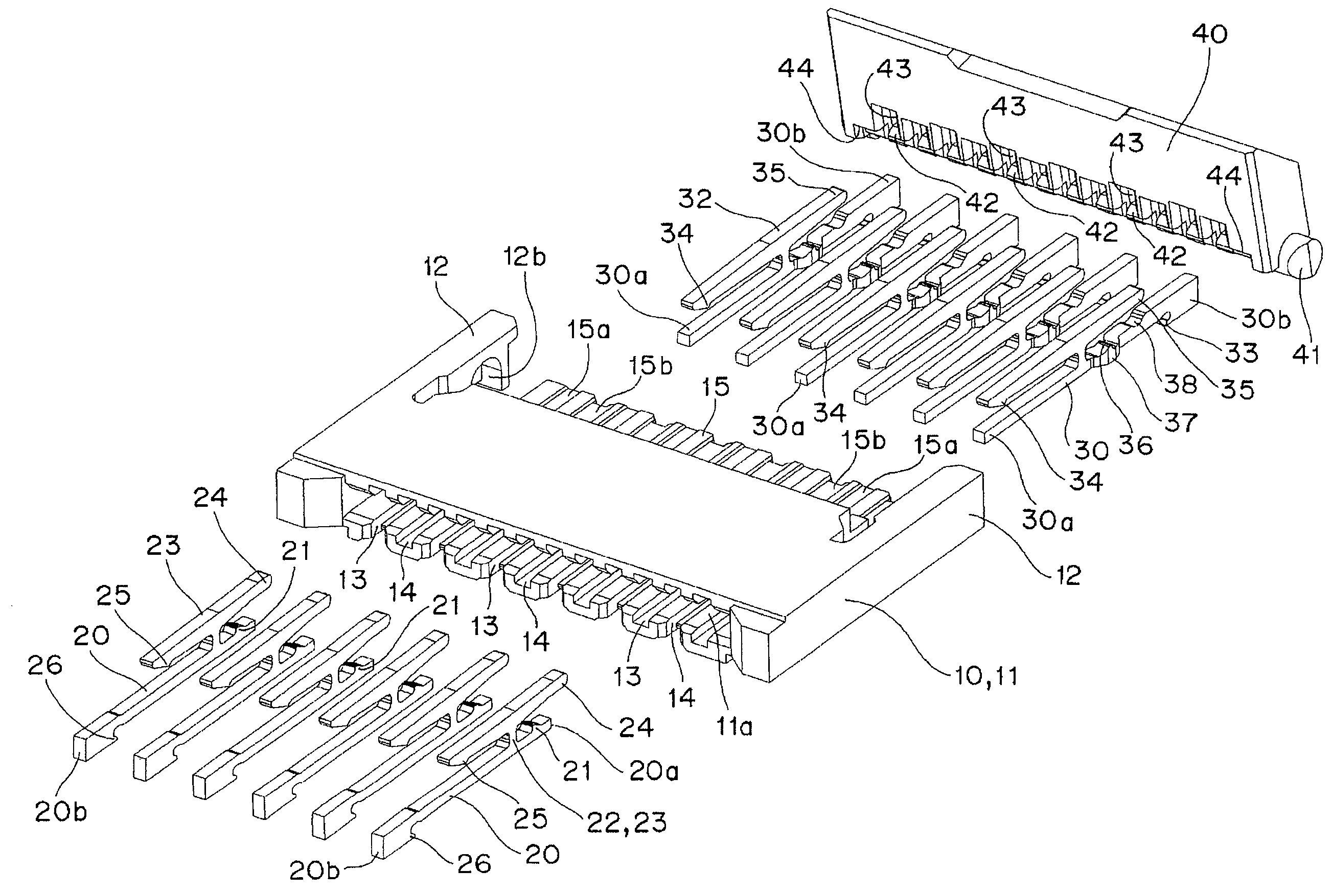
[0026]As shown in FIG. 1, a connector 10 according to a first embodiment roughly includes a base 11, a first connection terminal 20, a second connection terminal 30, and an operation lever 40.

[0027]As shown in FIGS. 9A and 9B, the base 11 has elastic arms 12, 12 extending in parallel at a rear surface side from one side edge on both side end faces. Of an inward surface of the elastic arm 12, a guide tapered surface 12a is formed at a distal end edge, and a bearing slit 12b is formed on a far side thereof.

[0028]As shown in FIG. 9A, the base 11 includes, on a front surface side, an opening 11a to which a distal end 51 of a flexible printed circuit board 50, to be hereinafter described, can be inserted, and has first insertion holes 13 passing from a front surface to a rear surface and being adjacently arranged at a predetermined pitch.

[0029]As shown in FIG. 9B, the bas...


PUM


Abstract

A connector connection terminal that is less likely to buckle and in which cutting task is facilitated is provided. The present invention provides a connector connection terminal in which substantial height dimension from a rotation recess to an end face at an end on a rear surface side is set larger than a substantial height dimension from the rotation recess to an end face at an end on the front surface side, and an upper surface from the rotation recess to the end face at the end on the rear surface side is a flat surface.

Description

BACKGROUND OF THE INVENTION[0001]1. Technical Field[0002]The present invention relates to connector connection terminals, in particular, to a connector connection terminal for connecting to a connecting portion arranged at a distal end of a flexible printed circuit board.[0003]2. Related Art[0004]Conventionally, for an FPC connector, for example, an FPC connector removably fitted with a flexible printed circuit board, the connector including required number of contacts having a contacting portion that contacts the flexible printed circuit board on both sides in an up and down direction, and a housing including a fit-in port to be held and fixed with the contact and to be inserted with the flexible printed circuit board, where the contacting portion in the up and down direction of the contact is arranged in a zigzag manner when a contact point with the contact of the flexible printed circuit board is arrayed in a zigzag manner (refer to, for example, Japanese Patent Application Laid-...

Claims


Application Information

Patent Timeline
IPC IPC(8): H05K1/00H01R12/88
CPCH01R12/79H01R12/88H01R12/68H01R13/629
Inventor HEMMI, YOSHINOBUTERANISHI, HIROTADA
Owner DAIICHI SEIKO CO LTD
Why Eureka
Try Eureka