
Release coated paper-attached label and label printer

a label printer and release technology, applied in the direction of identification means, instruments, sensing by electromagnetic radiation, etc., can solve the problems of limited information input capacity, high unit cost due to the licenser himself, and affect the accuracy of reading, etc., and achieve the effect of reducing the cost of the label printer

Inactive Publication Date: 2009-07-02
MAX CO LTD
View PDF7 Cites 19 Cited by
  • Summary
  • Abstract
  • Description
  • Claims
  • Application Information

AI Technical Summary

Benefits of technology

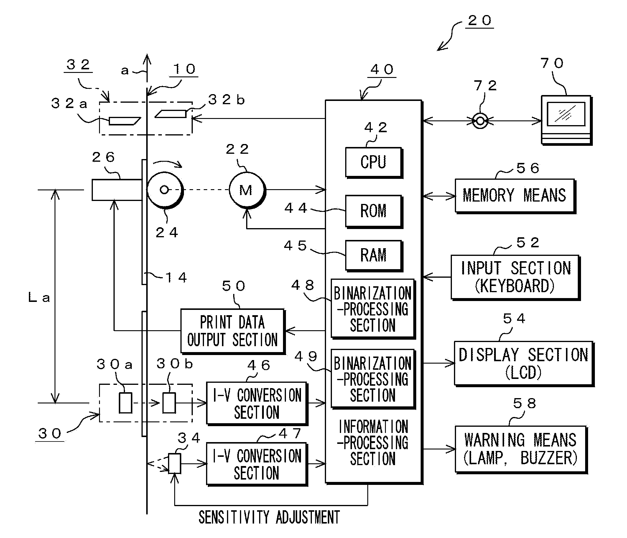
[0032]The present invention provides a release coated paper-attached label in which a mark indicating information related to a print quality is printed together with a barcode on a sheet of release coated paper. It also provides a label printer that comprises a reading sensor for reading a barcode printed on one side of a sheet of release coated paper for a label and a mark which is utilized as information related to a print quality and a control section for conducting print control and performing information processing related to the print quality based on information of this barcode and information of this mark which have been read.
[0033]Accordingly, the present invention has a feature that, by printing an identification mark prior to a barcode, this identification mark can be utilized as mark-checking information.
[0034]Further, according to this invention, by configuring an identification mark by sequentially shifting a plurality of identical marks in a traveling direction, even a reading sensor constituted of a single light-emitting element and a single photoreceptor element can acquire mark information on the identification marks, thereby reducing costs of the label printer. The present invention has another feature that, by checking the read mark information and the barcode information against each other, it is possible to certainly decide whether a related product is genuine.
[0035]Moreover, if the mark is used as a density information mark, it can be utilized to adjust sensitivity in a reading sensor, so that a barcode can be read without any errors and so can be analyzed correctly.

Problems solved by technology

If a reading sensor, by which a barcode is read, has fluctuations in its reading accuracy, the reading accuracy may be affected.
Although print information can be input using an operation key equipped to the label printer, in which case a capacity of information that can be input is limited, the print information is typically created using a terminal apparatus such as a personal computer.
If, for example, a CCD sensor mainly used presently is employed as means for reading a shared-use identification mark as described above, a unit cost due to a licenser himself is expensive, which leads to an increase in costs of the label printer itself.
In a possible case where the reading sensor is configured using light-emitting elements and photoreceptor elements, a lot of these elements must be used, which increases the costs inevitably.

Method used


Image

  • Release coated paper-attached label and label printer
  • Release coated paper-attached label and label printer
  • Release coated paper-attached label and label printer

Examples


first embodiment

[0074]The first embodiment relates to an embodiment of a release coated paper-attached label in which a mark that indicates information related to a print quality is used as an identification mark and a label printer used therein.

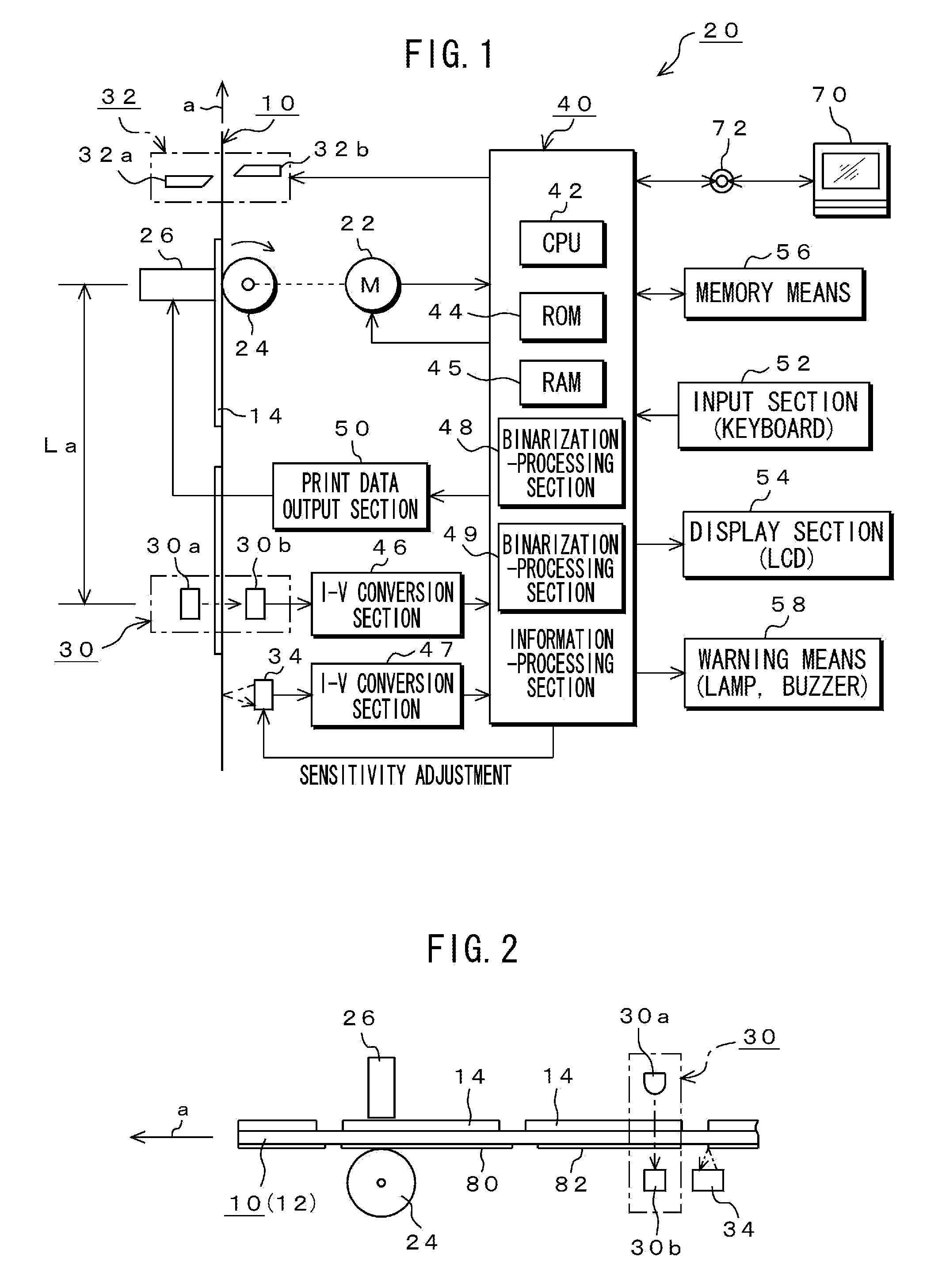
[0075]FIG. 1 is a system diagram of important components of a label printer 20 related to the present invention. FIGS. 4A and 4B show one example of important portions of a release coated paper-attached label 10 related to the present invention. First, the release coated paper-attached label 10 will be described with reference to FIGS. 4A and 4B.

[0076]The release coated paper-attached label 10 is constituted of a sheet of release coated paper 12 and a plurality of label pieces 14 which are stuck on one side, in this example, a surface side 12a of the sheet thereof. The sheet of release coated paper 12 is a strip-shaped mount, as which a translucent film is used in this example.

[0077]Each of the label pieces 14 is made of heat sensitive paper, and several ty...

second embodiment

[0125]Although the above-described mark 80 that indicates information related to the print quality has also been used as a density information mark, it can be configured as follows in order to be provided with only functions of the density information mark. The following exemplifies a case where the present invention is applied to a release coated paper-attached label 10 having a different mode from that shown in FIGS. 4A and 4B, in which individual information is printed beforehand in part of each of the label pieces 14 stuck on one side (surface side) of the sheet of release coated paper 12.

[0126]In the case of FIG. 10A, a predetermined lower area of each of the label pieces 14 with respect to a label traveling direction “a” is configured as to be formed as a printed area 14a. In this printed area 14a, predetermined information is printed. This predetermined information printed beforehand refers to individual identification information. The individual identification information ma...

third embodiment

[0147]The above-described label pieces 14 are divided into virginal label pieces each having no printed area and label pieces each having a printed area 14a partially. In either type, it is necessary to print character in a predetermined area of each of the label pieces 14. One example to accurately perform this print processing will be described with reference to FIGS. 13A and 13B.

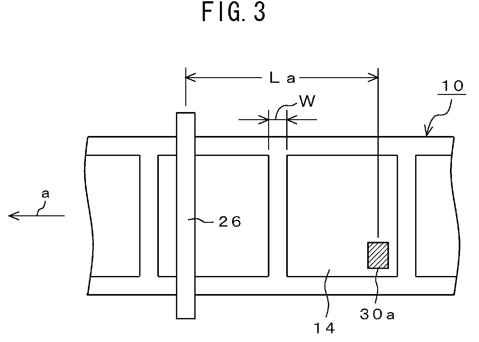
[0148]First, as shown in FIG. 13A, the label pieces 14 are produced by die-cutting them. Therefore, the label pieces 14 are arranged in a longitudinal direction of a sheet of release coated paper 12 with constant spacing W (W1, W2, W3, etc.) between them. Actually, the spacing fluctuates to some extent, so that W1, W2, and W3 are not equal to each other in many cases. In some cases, they may fluctuate by about 1-3 mm. In an example of FIG. 13A, they are die-cut in a condition where W2>W1 and W1>W3 on the assumption that W1 is a reference space setting.

[0149]Further, in this example, only one species of si...


PUM


Abstract

One reading sensor is used to read identification mark information, to decide whether a product is genuine.Identification marks each having sensitivity adjustment for the reading sensor and specific mark information are printed on a sheet of release coated paper. The sensitivity adjustment for the reading sensor is performed by utilizing information on a density acquired by reading the identification mark. By combining pieces of density information on a plurality of marks that constitutes the identification mark, mark information is generated. This mark information is checked against saved mark information. In this case, by utilizing the identification mark in which the plurality of identical marks are sequentially shifted in a traveling direction, even a reading sensor constituted of a single light-emitting element and a single photoreceptor element can acquire the mark information on the identification marks. The read mark information and the mark information contained in barcode information are checked against each other and, if they agree, it is decided that the product is genuine and a result of the decision is displayed.

Description

TECHNICAL FIELD[0001]The present invention relates to a release coated paper-attached label and a label printer for printing this label piece.[0002]More specifically, it relates to a release coated paper-attached label and the like in which, by printing on a back side of a sheet of release coated paper a barcode indicating related information of the label piece and a mark indicating information related to a print quality, if using the mark indicating the information related to the print quality as an identification mark, this identification mark can be utilized as genuine product information, and if using the mark indicating the information related to the print quality as a density information mark, this information can be utilized to adjust a sensitivity of a reading sensor.BACKGROUND ART[0003]A printer referred to as a label printer has been actively used in daily duties in all industrial fields for printing labels including labels for a variety of types of products as well as lab...

Claims


Application Information

Patent Timeline
Patent Type & Authority Applications(United States)
IPC IPC(8): G09F3/00B41J2/01B41J29/38G06K7/10
CPCB41J2/36G06K1/20G06K7/10762Y10T428/1486G09F3/0297G09F2003/0201B41J11/009G06K19/14
Inventor HORIKOSHI, NAOYA
Owner MAX CO LTD
Learn More