
Drilling Tool Steering Device

a steering device and drilling tool technology, applied in the direction of drilling casings, drilling pipes, directional drilling, etc., can solve the problems of not being able to provide steering drilling tools in all the required configurations, the length of the bent housing cannot be reduced without compromising the life, etc., to achieve reliable and economical manufacturing, easy mounting and maintenance, and the effect of reducing the length

Active Publication Date: 2009-07-02
MILLET
View PDF21 Cites 74 Cited by
  • Summary
  • Abstract
  • Description
  • Claims
  • Application Information

AI Technical Summary

Benefits of technology

[0017]One objective of the invention is to propose a steering device architecture, also called “steerable connection” or “adjustable bent housing connection,” making it possible to overcome the limitations indicated above. Such a device has a reduced length and, consequently, offers a high BUR in spite of a narrow tilt angle (or steering angle), is also reliable and economical to manufacture and makes easy mounting and maintenance possible.

Problems solved by technology

With the methods most commonly used for making a static steerable connection placed at the end of a drill string, the length of the bent housing cannot be reduced without compromising the life of the thrust bearing used as support for the drilling tool.
According to that state of the art, means were not available for steering drilling tools in all the required configurations.

Method used


Image

  • Drilling Tool Steering Device
  • Drilling Tool Steering Device
  • Drilling Tool Steering Device

Examples


Embodiment Construction

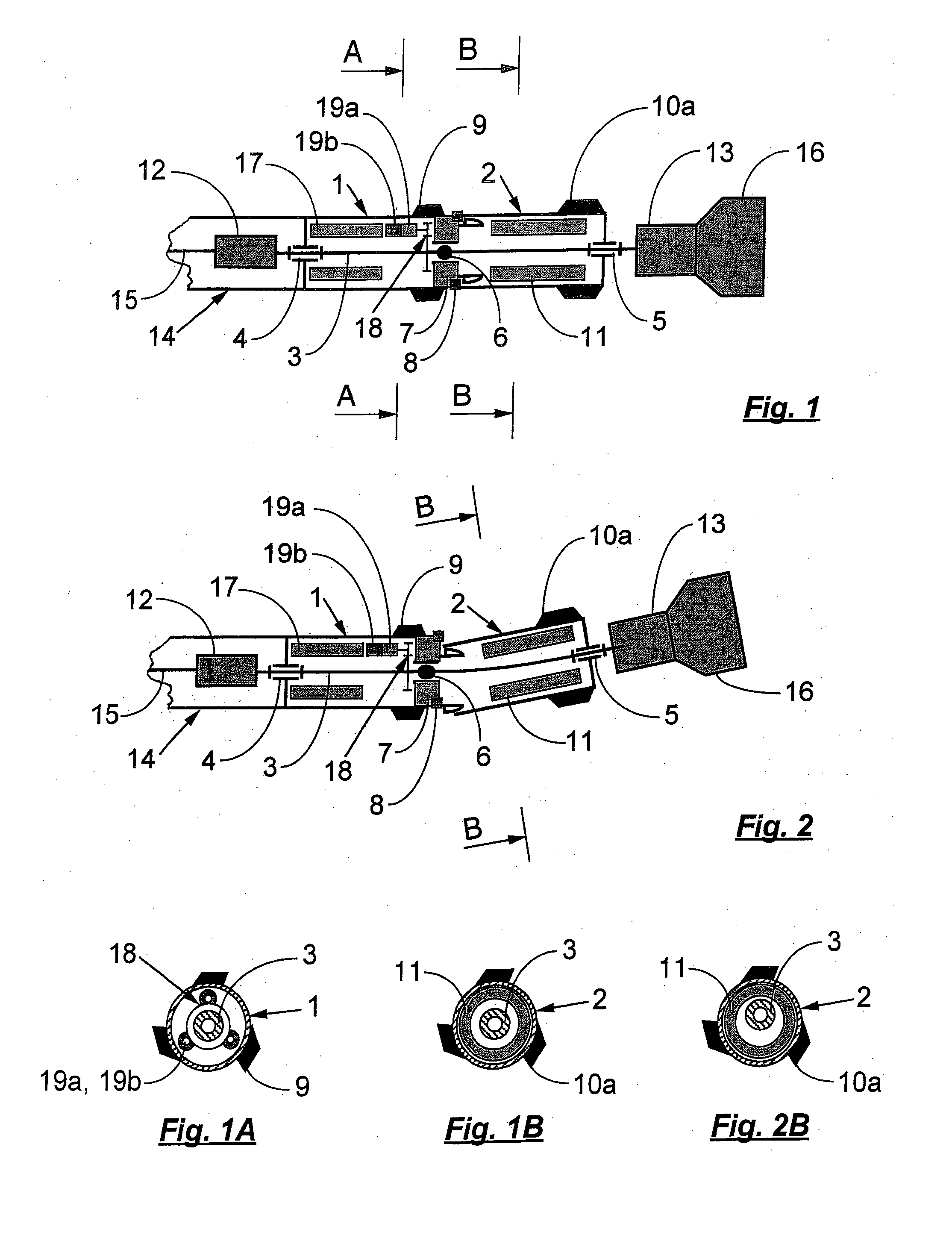
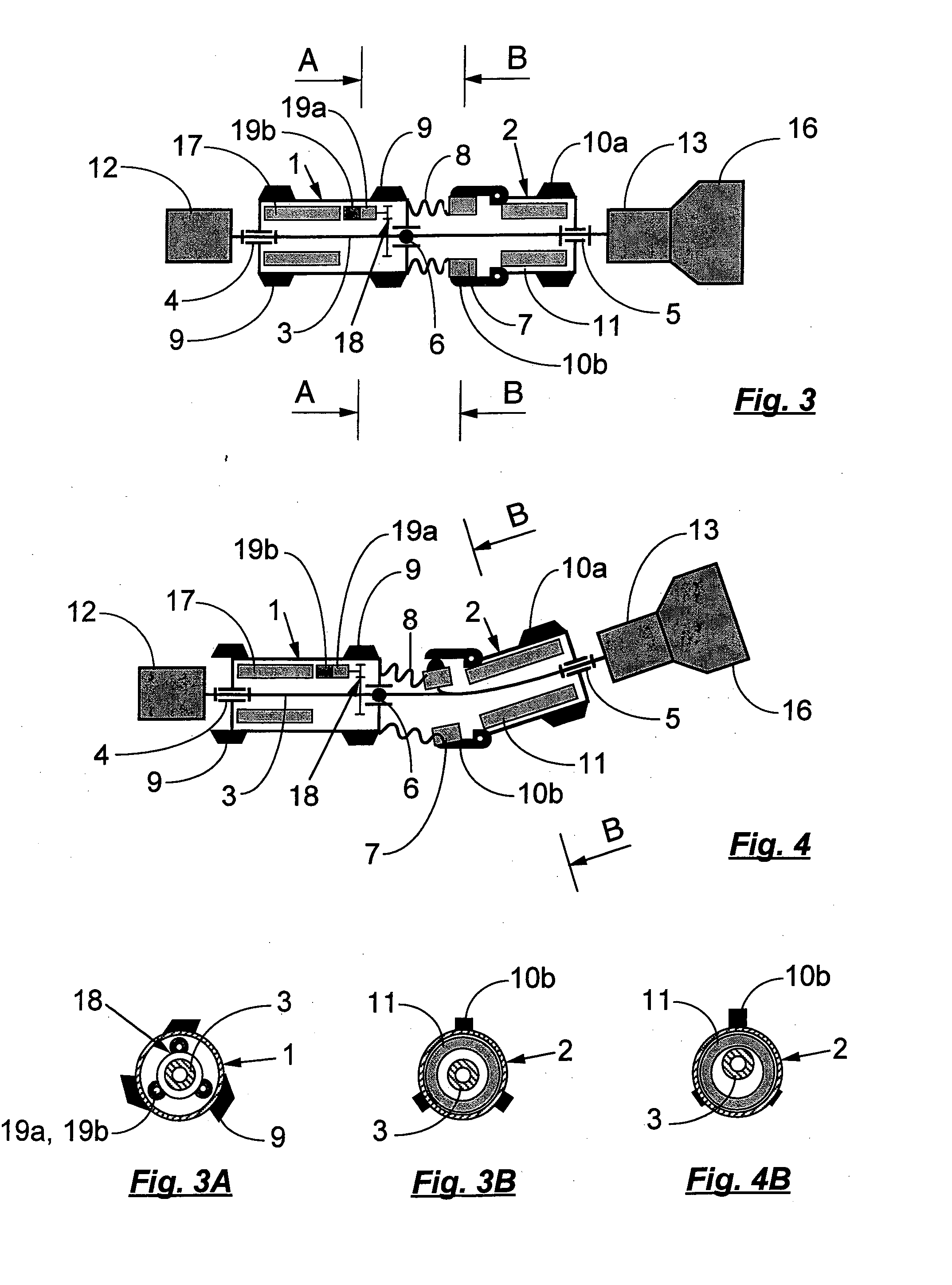
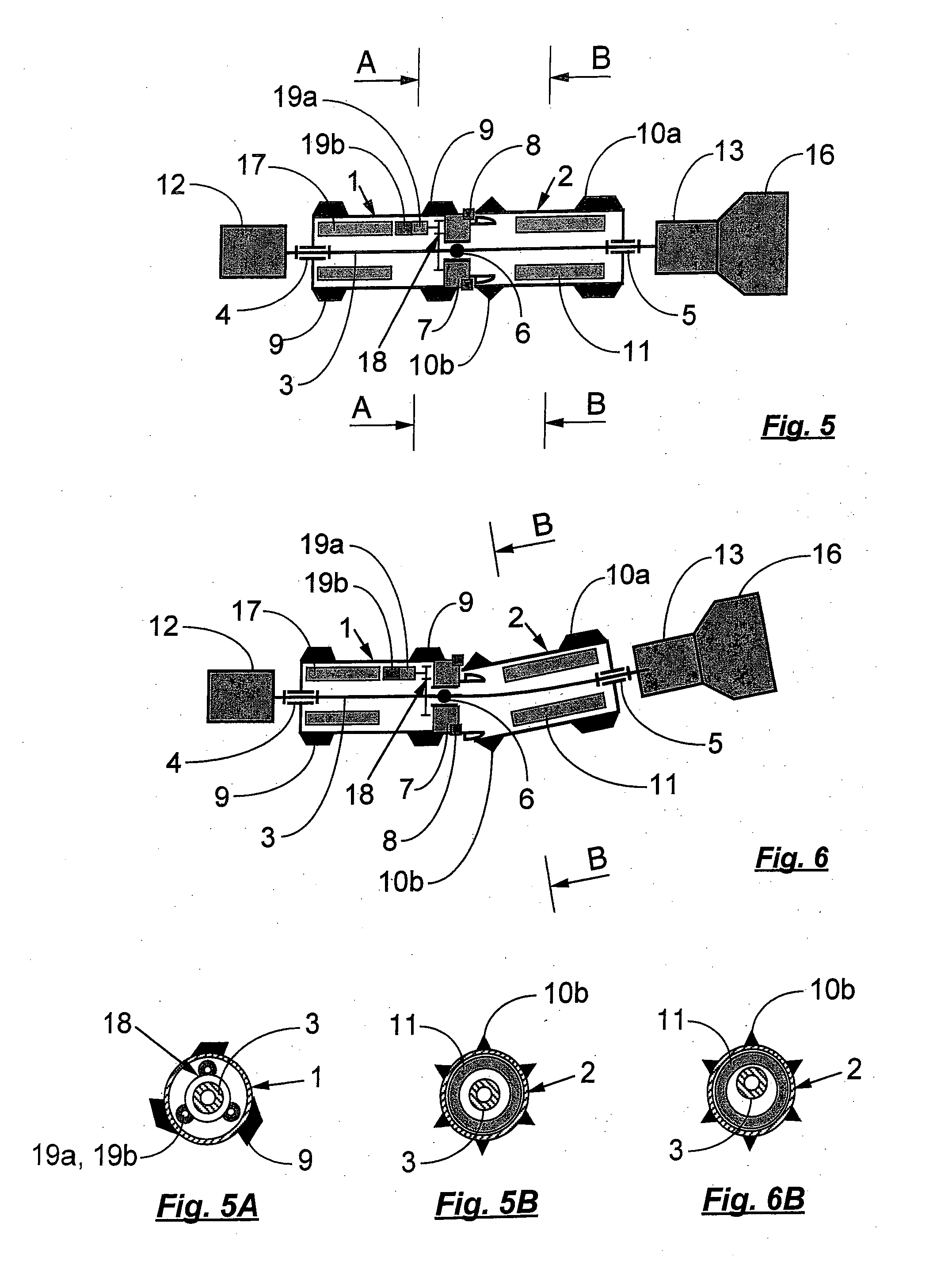
[0044]With reference to the drawings thus briefly described, notably FIGS. 1-8, which illustrate but in no way limit it, the device having a steerable connection architecture according to the invention essentially contains a main body 1 and a steerable housing 2, joined respectively by at least one connection of pivot, sliding pivot, ball joint or annular linear type forming a first bearing 4, and at least one pivot connection for a second bearing 5, to a bendable or flexible transmission shaft 3 which crosses them longitudinally,

[0045]while an appropriate connection forming a third bearing 6 between said transmission shaft and the main body is arranged in proximity to the interface between said main body and said housing, and

[0046]while steering is carried out thanks to means acting as a deflection system 7 in order to control the essentially radial displacement of the main body 1 in relation to the steerable housing 2 in proximity to their interface,

[0047]the said main body being ...


PUM


Abstract

The invention concerns a drilling tool steering device, characterized in that it contains, consecutively from upstream to downstream, a main body (1) and a steerable housing (2), joined respectively by at least one connection of pivot, sliding pivot, ball joint or annular linear type forming a first bearing (4), and at least one pivot connection forming a second bearing (5), to a bendable or flexible transmission shaft (3) which crosses them longitudinally, while a connection of pivot, sliding pivot, annular linear or ball joint type forming a third bearing (6) between said transmission shaft and the main body (1) is arranged in proximity to the end of said main body situated in the direction of the steerable case, and while steering is carried out thanks to means acting as a deflection system (7) for the essentially radial relative displacement of the main body (1) in relation to the steerable housing (2) in proximity to their interface, the said main body being optionally equipped on its periphery with bearing pads (9) of diameter less than or equal to the diameter of the drilling tool / bit (16), and the said steerable case being optionally equipped on its periphery with bearing pads (10a) of diameter less than or equal to the diameter of the drilling tool / bit (16) toward its end situated in the direction of the drilling tool / bit, and with fixed or expandable pads or clamps toward its end situated in the direction of the main body (1). Application to boreholes necessitating trajectory control.

Description

FIELD OF THE INVENTION[0001]The present invention concerns the field of drilling. It concerns, in particular, drilling that necessitates trajectory control, notably in the fields of the petroleum and gas industry, civil engineering, geothermics and, in general, in all fields of trenchless underground operations.[0002]In some of these fields, the drilling systems employed can be entirely mechanical or else include electronic equipment. These systems are roughly defined as follows:[0003]Static device: steerable connection, also called adjustable bent housing, adjusted on the surface to equip a turbine type downhole power section, PDM (“Positive Displacement Motor”) or electric motor;[0004]Pseudodynamic device: steerable connection activated autonomously or from the surface, solely for the non-rotative sliding phases of the boring rods, designated by the English-language term “sliding,” to equip a downhole power section of turbine type, or else stabilizing type of activated variable di...

Claims


Application Information

Patent Timeline
IPC IPC(8): E21B7/08E21B7/04E21B7/06
CPCE21B17/04E21B7/067
Inventor MILLET
Owner MILLET
Learn More