Vacuum suction device

a vacuum suction device and vacuum technology, applied in the field of vacuum suction devices, can solve problems such as deteriorating the optical performance of the lens modul

Inactive Publication Date: 2009-06-25
HON HAI PRECISION IND CO LTD
View PDF8 Cites 1 Cited by
  • Summary
  • Abstract
  • Description
  • Claims
  • Application Information

AI Technical Summary

Problems solved by technology

Therefore, the electrostatic repulsion between different parts may move the assembled parts away from their predetermined position, thereby deteriorating the optical performance of the lens module.

Method used


Image

  • Vacuum suction device
  • Vacuum suction device
  • Vacuum suction device

Examples


Embodiment Construction

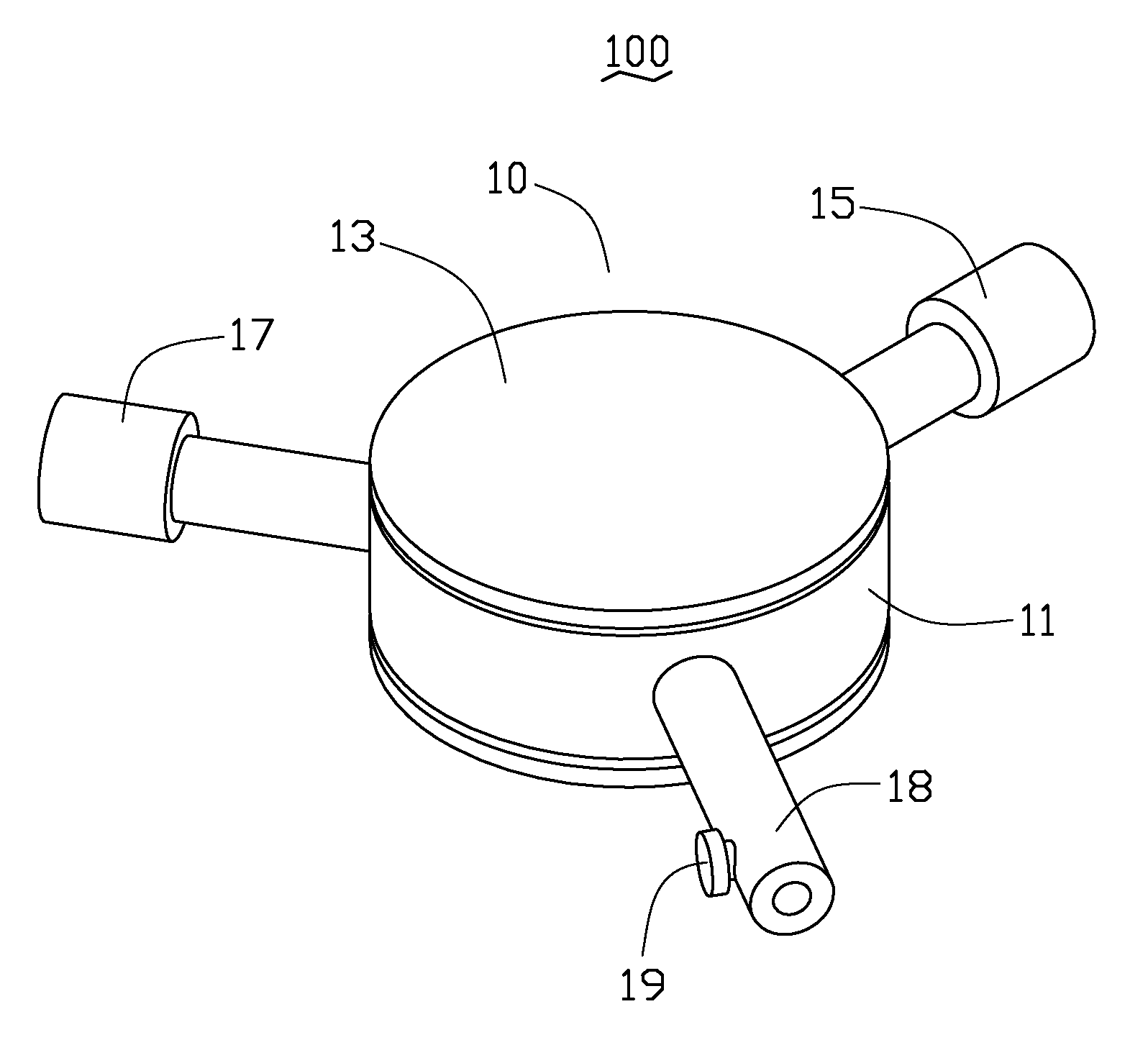
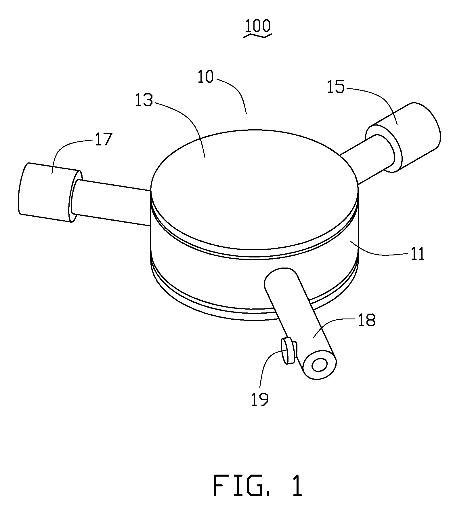
[0013]Referring to FIGS. 1 and 2, a vacuum suction device 100 in accordance with a first embodiment includes a switch valve 10, a vacuum pump 15, an ion generator 17, and a vacuum picking member 18.

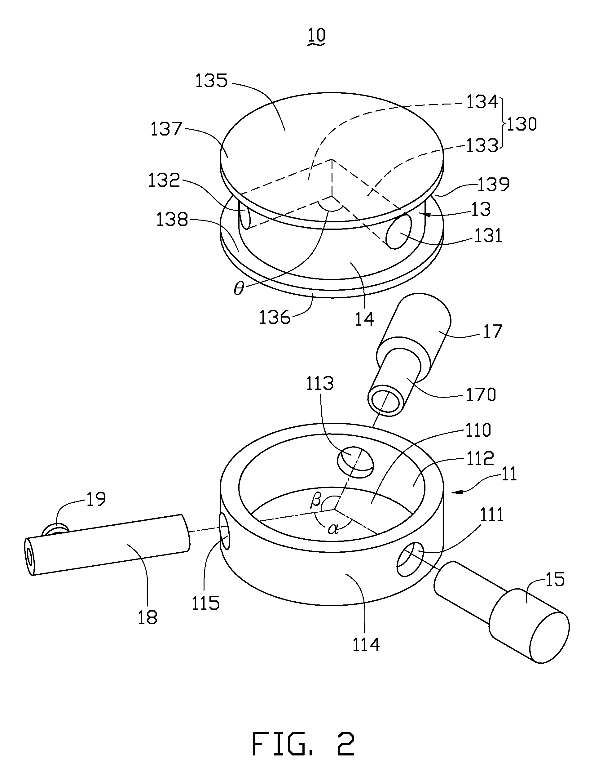
[0014]The switch valve 10 includes an outer enclosure 11 and an inner cylindrical body 13 rotatably received in the outer enclosure 11. The outer enclosure 11 is columnar and has a circumferential inner wall surface 112, a circumferential outer wall surface 114 and a cylindrical through hole 110 surrounded by the circumferential inner wall surface 112. An outer diameter of the inner cylindrical body 13 is equal to an inner diameter of the outer enclosure 11. Therefore, the inner cylindrical body 13 is received in and is in tightly contact with the outer enclosure 11.

[0015]The outer enclosure 11 includes a first through opening 111, a second through opening 113, and a third through opening 115 formed in a sidewall thereof. The first through opening 111, the second through opening 113, and ...


PUM


Abstract

A vacuum suction device includes an inner cylindrical body, an outer enclosure, a vacuum pump, an ion generator, and a vacuum picking member. The inner cylindrical body has a through hole defined therein. The inner cylindrical body is received in a through hole of the outer enclosure and is rotatable relative to the outer enclosure such that the through hole alternatively couples the vacuum picking member to one of the vacuum pump and the ion generator. The vacuum pump is coupled to the third through opening of the outer enclosure. The ion generator is coupled to the second through opening of the outer enclosure. The vacuum picking member is configured for picking a workpiece, the vacuum picking member being coupled to the first through opening of the outer enclosure.

Description

BACKGROUND[0001]1. Technical Field[0002]The present invention generally relates to a vacuum suction device, and particularly relates to a vacuum suction device for picking optical components during assembling of lens module.[0003]2. Discussion of Related Art[0004]Camera modules are widely used in various most popular portable electronic devices such as mobile phones, laptop computers and personal digital assistants (PDAs). Generally, a camera module includes a lens module and an image sensor (e.g. a Charge Coupled Device (CCD) image sensor or a complementary metal oxide semiconductor (CMOS) image sensor). Optical performance of the lens module is very important to a camera module.[0005]A lens module generally includes a barrel holder, a barrel held on the barrel holder, and a number of optical members (i.e. filters, micro lenses) and structural members (i.e. spacers, gaskets) assembled in sequent in the barrel. To obtain a high optical performance, the optical members and structural...

Claims


Application Information

Patent Timeline
Patent Type & Authority Applications(United States)
IPC IPC(8): B65H1/00
CPCG02B27/62B25B11/007
Inventor LIN, DA-WEI
Owner HON HAI PRECISION IND CO LTD
Why Eureka
Try Eureka