Fuel injection valve
a fuel injection valve and valve body technology, applied in the direction of fuel injection apparatus, fuel feed system, spraying apparatus, etc., can solve the problems of increasing difficult to control the quantity, and disadvantageously reducing the minimum controllable injection quantity
- Summary
- Abstract
- Description
- Claims
- Application Information
AI Technical Summary
Benefits of technology
Problems solved by technology
Method used
Image
Examples
first embodiment
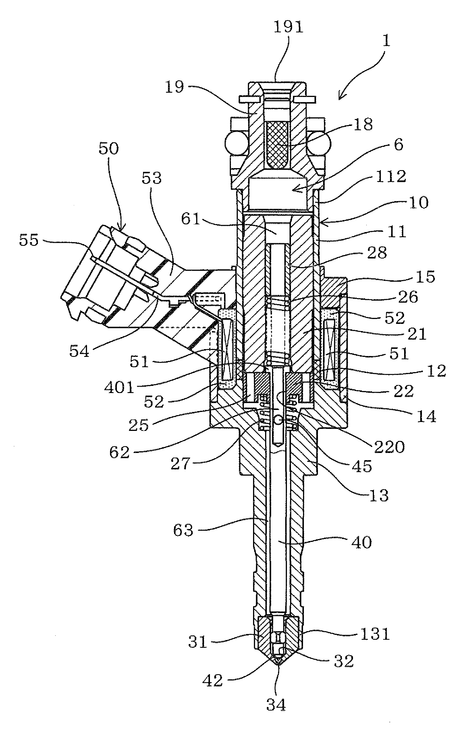
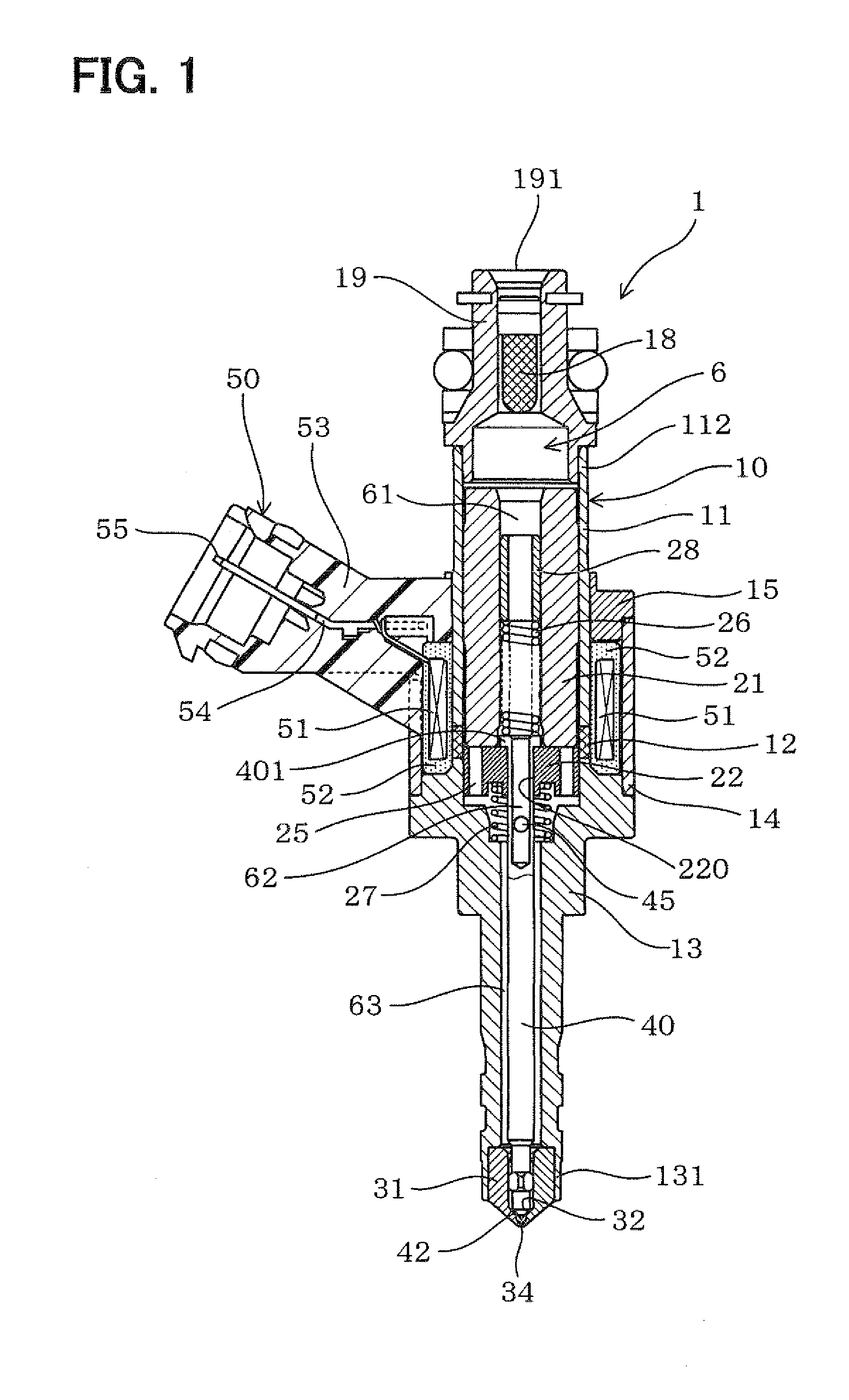
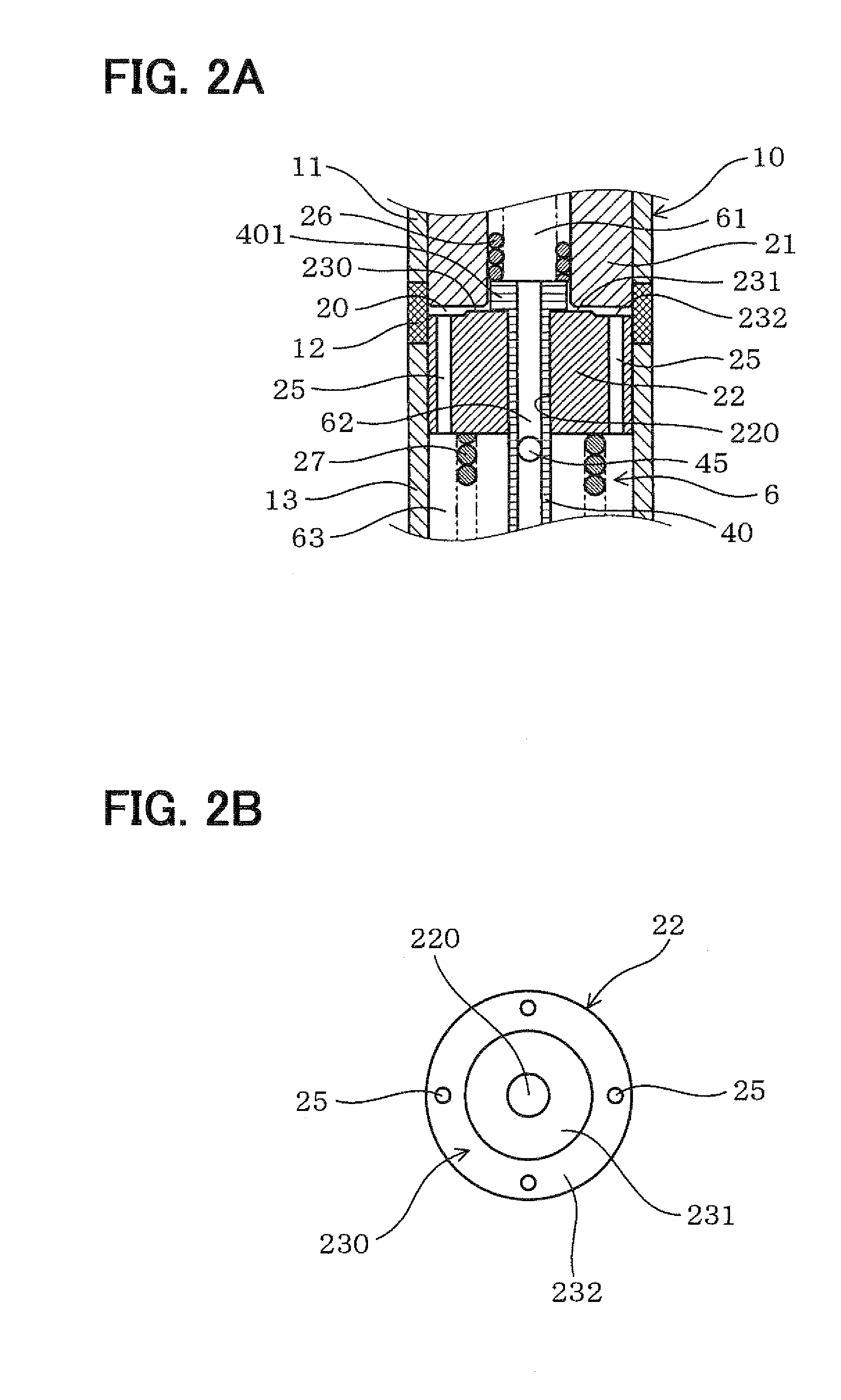
[0041]FIGS. 1, 2A, 2B, and 3 show a fuel injection valve (an injector) 1 according to the first embodiment of the present invention.
[0042]With reference to FIG. 1, the fuel injection valve 1 is mounted on the head of a direct-injection gasoline engine (not shown) but may be alternatively used for an indirect-injection gasoline engine or a diesel engine,
[0043]The fuel injection valve 1 has a nozzle hole 34 formed at a front end of the valve 1. The front end of the fuel injection valve 1 corresponds to a downstream side of the fuel injection valve 1 in a flow direction of fuel. Also, a rear end of the fuel injection valve 1 corresponds to an end of the valve 1 opposite from the front side, and corresponds to an upstream side of the valve 1 in the flow direction.
[0044]The fuel injection valve 1 includes a tubular housing 10 that defines a fuel channel 6 therein. The housing 10 includes a pipe 11, a tubular non-magnetic part 12, and a tubular holder 13, which are integrated with each ot...
second embodiment
[0088]FIGS. 5A to 7B show fuel injection valves according to the second embodiment of the present invention. In each of these valves, the movable core 22 has communicating passages 25 positioned differently from those in the first embodiment.
[0089]In each of FIGS. 5A, 6A, and 7A, the movable core 22 is in contact with the stator 21.
[0090]FIGS. 5A and 5B show a fuel injection valve in which the movable core 22 has four communicating passages 25 formed to extend through the movable core 22 as is the case with the first embodiment.
[0091]In FIGS. 5A and 5B, the communicating passages 25 are rectangular in section and positioned at intervals of 90 degrees near the outer periphery of the movable core 22.
[0092]In this case, the second communicating passage 25 sufficiently has the effect of improving the responsibility of the valve member 40, and thereby improving the injection characteristic of the fuel injection valve 1. In addition, the second communicating passage 25 is easy to form by ...
third embodiment
[0099]FIGS. 8A to 11B show fuel injection valves according to the third embodiment of the present invention. In each of these valves, the stator 21 defines communicating passages 24 therein in place of the communicating passages 25 of the movable core 22 in the first and second embodiments,
[0100]As shown in FIGS. 8A to 11B. the stator 21 defines the communicating passages 24 that connect the annular space 20 with the fuel passage 61, which corresponds to the first fuel passage of the fuel channel 6 positioned upstream of the movable core 22.
[0101]In each of FIGS. 8A, 9A, 10A, and 11A, the movable core 22 is in contact with the stator 21.
[0102]FIGS. 8A to 9B show fuel injection valves in each of which the stator 21 defines four communicating passages 24 therein that extend through the stator 21.
[0103]More specifically, in FIGS. 8A and 8B, the communicating passages 24 extend open at the inner peripheral surface 211 of the stator 21 and to open at the front end face 210 of the stator,...
PUM
 Abstract
Description
Claims
Application Information
 - R&D Engineer
- R&D Manager
- IP Professional
- Industry Leading Data Capabilities
- Powerful AI technology
- Patent DNA Extraction
Browse by: Latest US Patents, China's latest patents, Technical Efficacy Thesaurus, Application Domain, Technology Topic, Popular Technical Reports.
© 2024 PatSnap. All rights reserved.Legal|Privacy policy|Modern Slavery Act Transparency Statement|Sitemap|About US| Contact US: help@patsnap.com


