On-demand lubrication system and method for improved flow management and containment
a technology of flow management and containment system, which is applied in the direction of pressure lubrication, machines/engines, mechanical equipment, etc., can solve the problems of increasing the risk of auto-ignition, and difficulty in maintaining sufficient air curtains to contain oil in pressurized compartments. achieve the effect of increasing the rate and reducing the amount of oil leakag
- Summary
- Abstract
- Description
- Claims
- Application Information
AI Technical Summary
Benefits of technology
Problems solved by technology
Method used
Image
Examples
first embodiment
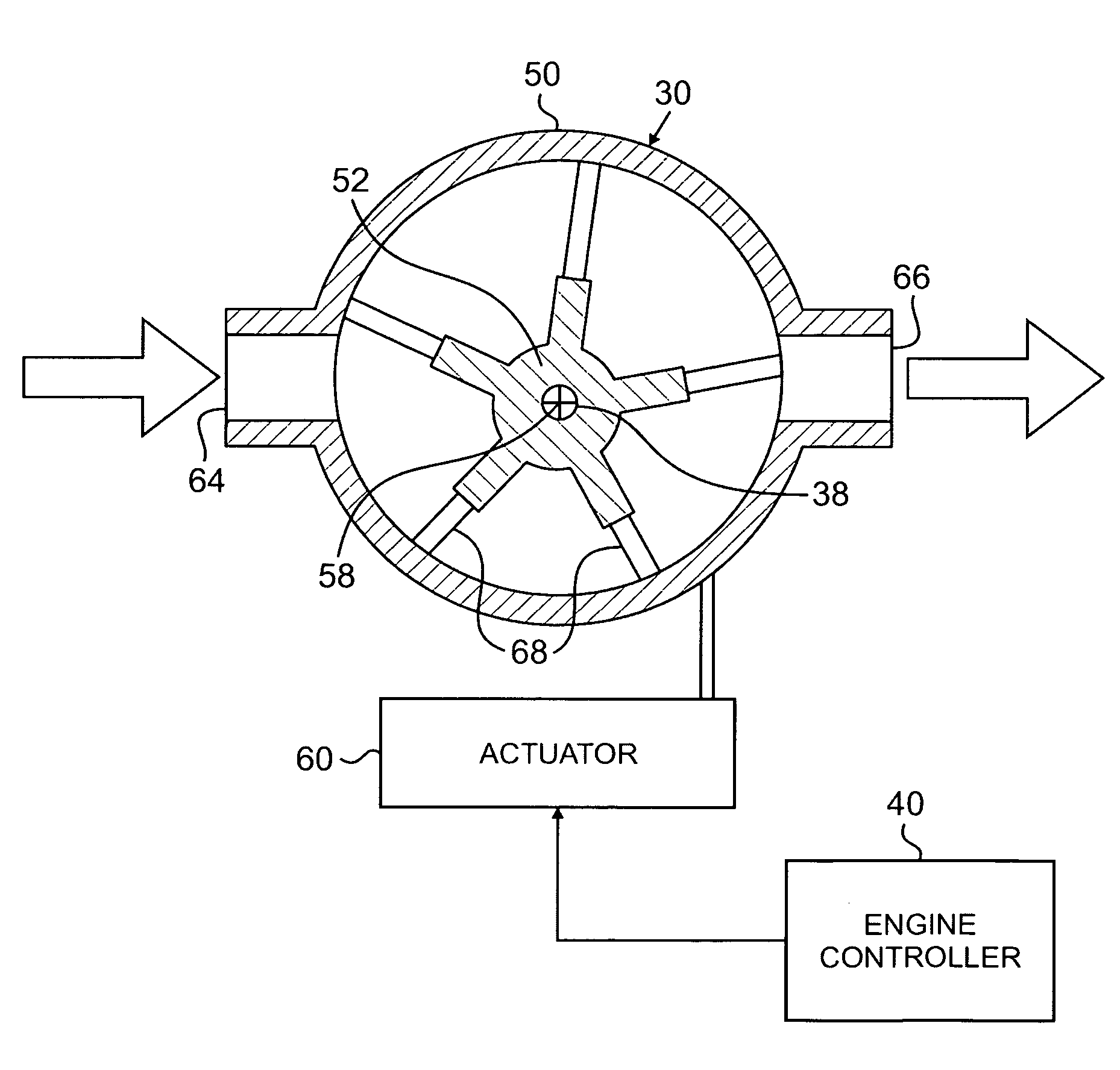
[0025]FIGS. 6A-6C are views of alternative embodiments of actuation and mechanical linkage assemblies for the lubricant distribution and containment system. FIG. 6A illustrates a first embodiment where the actuator 60 connected to the housing 50 of the scavenge pump 30 is mounted to an external “ground” location, and the actuator 62 connected to the housing 54 of the pressure pump 32 is mounted to an external “ground” location. Here, actuation of the actuator 62 moves both the housings 50 and 54, because the pin 72 will contact a circumferential extent of the slot 74. An additional actuation stroke can be achieved for the scavenge pump 30, as desired, through actuation of the actuator 60. Thus, the actuation stroke of the actuator 62 for the pressure pump 32 is ΔLA and the actuation stroke of the actuator 60 for the scavenge pump 30 is ΔLA+ΔLB. It should be noted that in FIG. 6A, the actuator 60 is shown in a fully extended state with ΔLB at its maximum and the pin 72 at one end of ...
second embodiment
[0026]FIG. 6B illustrates a second embodiment where the actuator 62 connected to the housing 54 of the pressure pump 32 is mounted to an external “ground” location and the actuator 60 for the scavenge pump 30 is supported by a beam (or support bracket) 76 extending from the housing 54 of the pressure pump 32. Similar to the embodiment of FIG. 6A, the actuation stroke of the actuator 62 for the pressure pump 32 is ΔLA and the actuation stroke of the actuator 60 for the scavenge pump 30 is ΔLA+ΔLB. Though in the embodiment of FIG. 6B, the movement of the housing 54 causes movement of the beam 76, which displaces the actuator 60 and in turn the housing 50. It should be noted that in FIG. 6B, the actuator 60 is shown in a fully extended state with ΔLB at its maximum.
third embodiment
[0027]FIG. 6C illustrates a third embodiment where the actuator 62 connected to the housing 54 of the pressure pump 32 is mounted to an external “ground” location and the actuator 60 is mounted between the housing 54 of the pressure pump 32 and a beam (or support bracket) 78 extending from the housing 50 of the scavenge pump 30. In this configuration, the actuators 60 and 62 are arranged to oppose one another. In this embodiment, the actuation stroke of the actuator 62 for the pressure pump 32 is ΔLA and the actuation stroke of the actuator 60 for the scavenge pump 30 is ΔLA+ΔLB. It should be noted that in FIG. 6C, the actuator 60 is shown in a fully extended state with ΔLB at its maximum.
[0028]It will be recognized by those of ordinary skill in the art that control of the actuators 60 and 62 can vary as desired for particular applications.
PUM
 Abstract
Description
Claims
Application Information
 - R&D
- Intellectual Property
- Life Sciences
- Materials
- Tech Scout
- Unparalleled Data Quality
- Higher Quality Content
- 60% Fewer Hallucinations
Browse by: Latest US Patents, China's latest patents, Technical Efficacy Thesaurus, Application Domain, Technology Topic, Popular Technical Reports.
© 2025 PatSnap. All rights reserved.Legal|Privacy policy|Modern Slavery Act Transparency Statement|Sitemap|About US| Contact US: help@patsnap.com


